
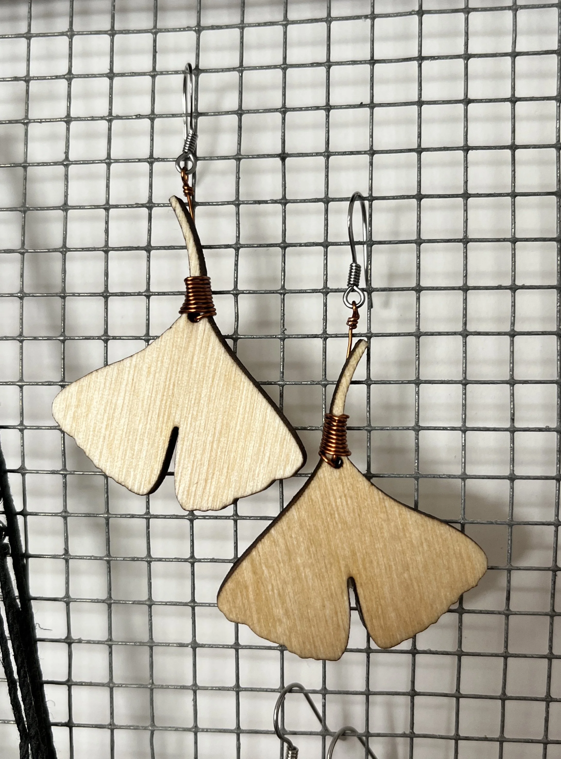
Just some Ginkgo Tree Leaf earrings I was commissioned to make.
Illustrator scripting: Convert all top level layers to groups
Spent the past 2 hours sorting this out… and posting in hopes it helps someone else.
With work I often receive Illustrator files exported from Rhino that have the wingsuit panels I need separated into layers but not groups, which I need in order to make my life easier moving panels around. I’ve been doing this manually for years, and only recently added a mouse button script to just group what was selected. So it was “click layer, click mouse button, click layer, click mouse button…” over and over until all layers were grouped individually, and there’s usually a lot of them. Doesn’t take forever but annoying.
I wanted a script to iterate through every top level layer, and group it. Pretty simple if you are a proficient coder. I’m not. So after banging my head against it, I finally got this script working:
if (app.activeDocument.layers.length > 1) {
for (var i = 0; i < app.activeDocument.layers.length; i++) //loop through all TOP LEVEL layers
{
app.activeDocument.layers[i].hasSelectedArtwork = true; //selects all in active layer
app.executeMenuCommand('group'); //groups all selected
app.activeDocument.selection = null; //deselect
}
} else {
alert("The active document only has only 1 layer");
}
I used the Adobe Illustrator scripting guide, this post, and this post (and a few others I forgot) as reference. I’m quite sure my code is dirty and needs variables etc… but it works so meh. I’ve been automating a bunch of tasks in Photoshop too, but they are super specific so not much help to others.
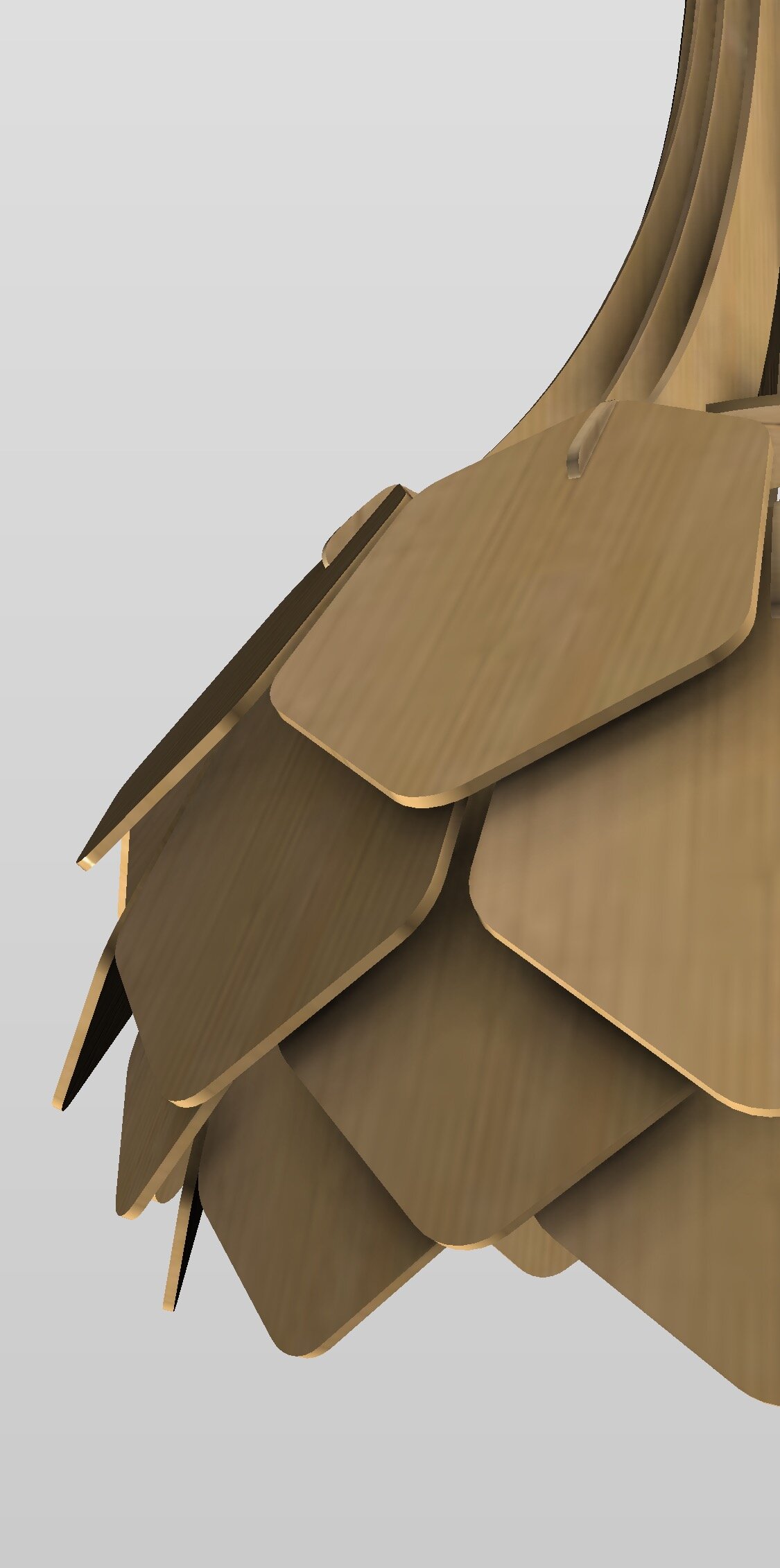
I love lamp
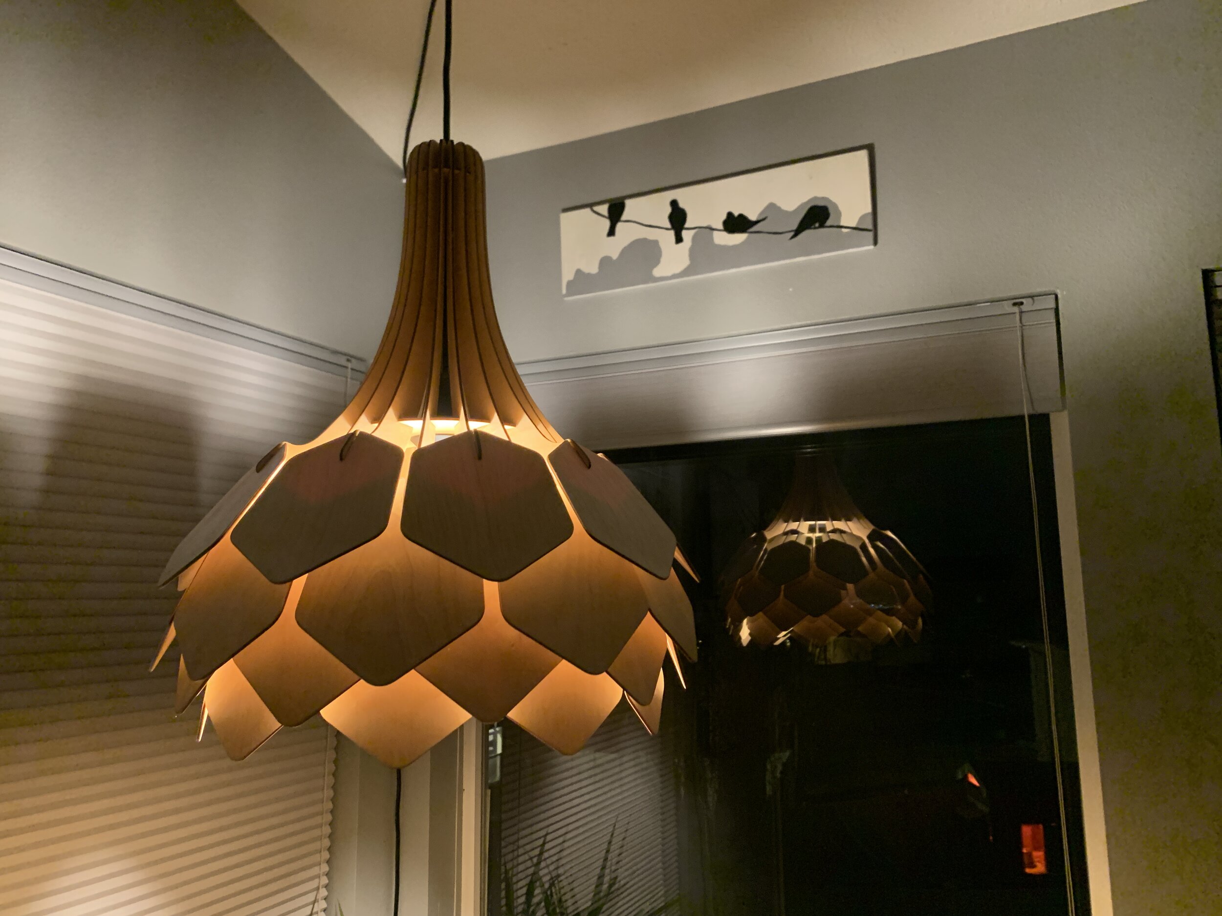
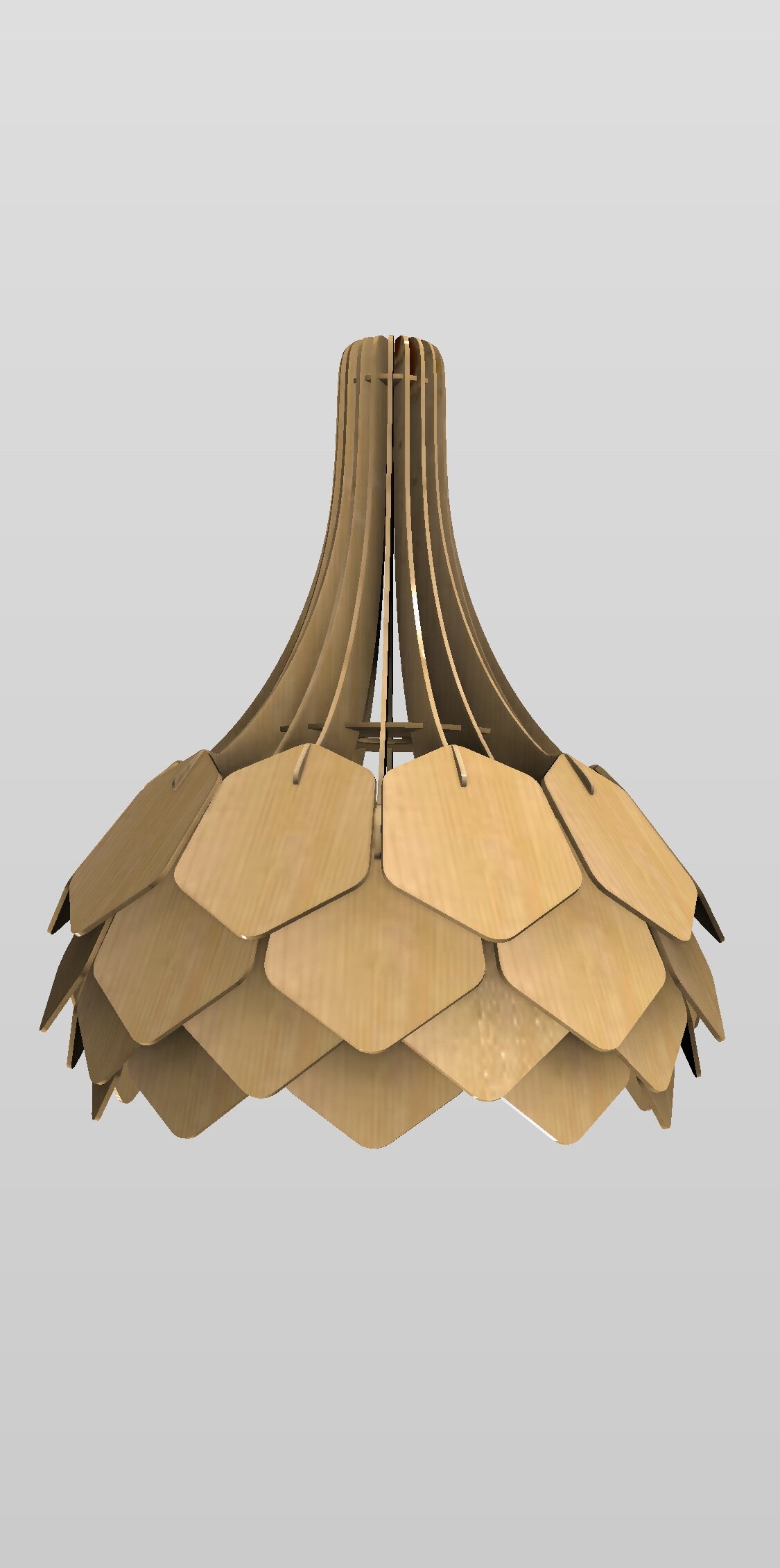
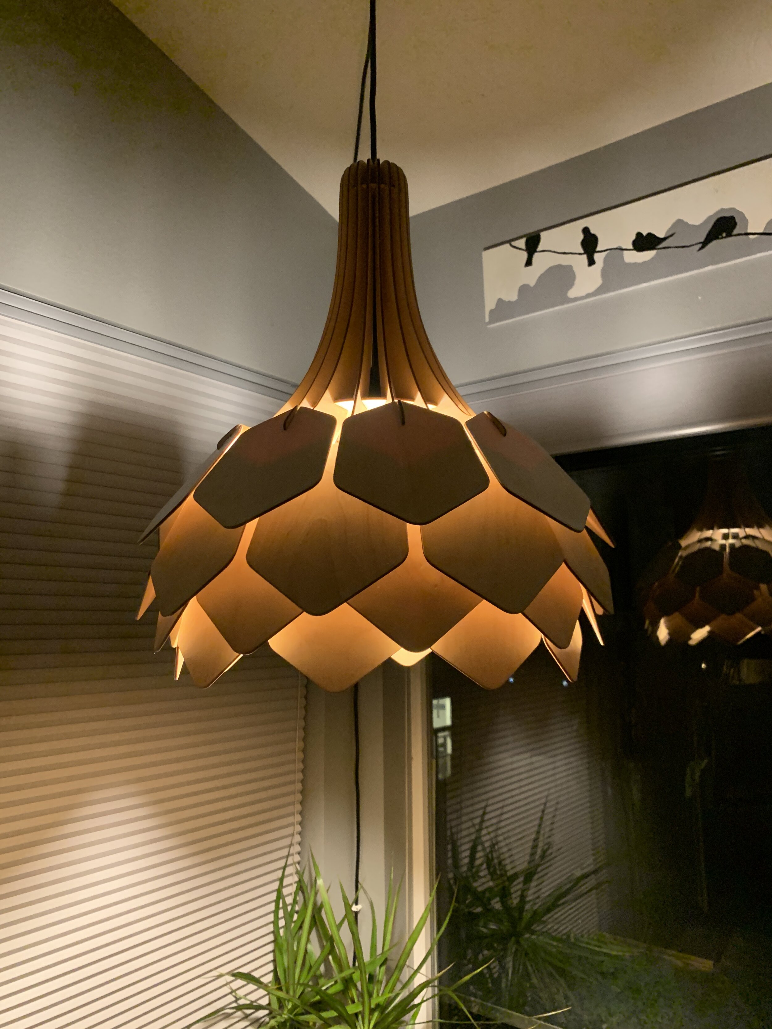
I saw an image of a laser cut lamp a couple years back that I’ve wanted to build ever since. I decided to use it to teach myself some Fusion 360 techniques in early 2020, so I modeled it up a few times in different ways so I could learn how to build the model parametrically (so you can change things like stock thickness, kerf, etc…) and export panels for laser cutting directly from Fusion 360. I got it 90% of the way there… and it got back burnered as so many projects do.
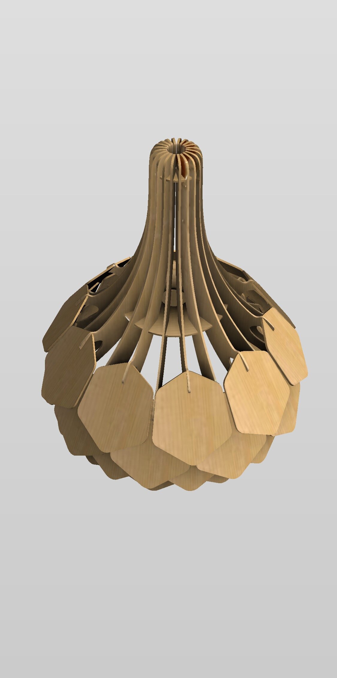
Over the holidays was the perfect time to load it back up and finalize the model so I could cut and create the panels. You can view the final model on the web (be sure to play with the “explode” feature… pretty fun)!
The current trick I’m using (this will likely change as Fusion 360 matures) for exporting vector files, DXF in this case, from Fusion 360 to be able to cut them on a laser is as follows:
When the model is finalized, Click “Create Sketch”, and select the planar face you want to export. Click “Finish Sketch”. This should make a new sketch layer with a red lock icon.
Right click this Sketch in the browser and you can then select “Save as DXF.”
This will get you a DXF file that you should be able to open in whatever vector based app you use to do your laser cutting prep, in my case Illustrator.
This works well for Polyline based curves but anything that is Spline based ends up exporting pretty low resolution. For those I had to use the “DXF Spline to Polyline” plug-in and crank up the sections to something usable, which I then simplified in Illustrator using path simplification. This works really well to get nice curves and keeps the slots in tact.
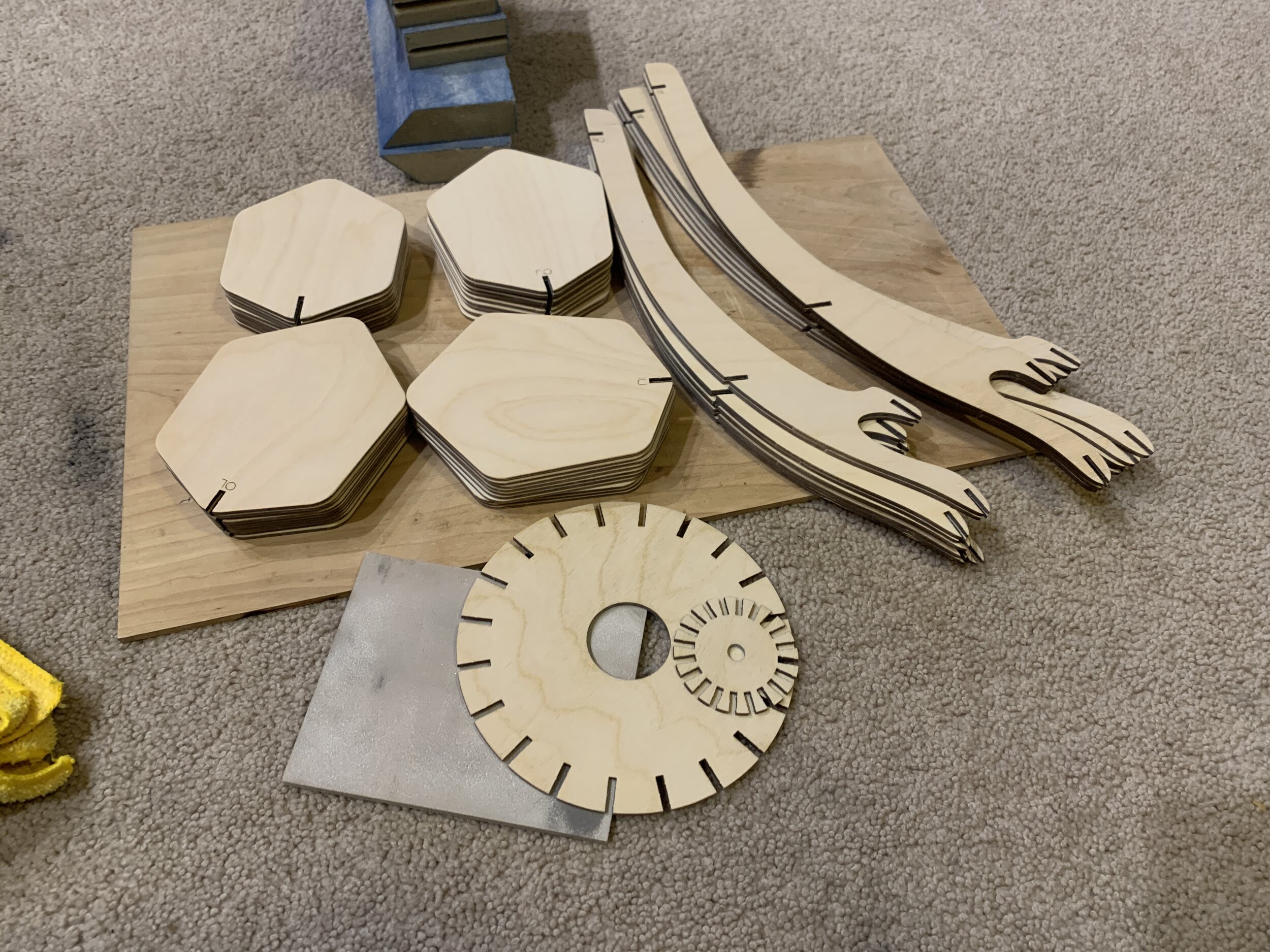
I ended up adding slot “nibs” for the first time and what a huge revelation these are. This allowed me to not think much about the kerf and just model the joining slots with the measurements of the stock, 3mm birch ply in this case, and after adding the nibs, the pieces fit together really nice. I added these in Illustrator afterward, but will set them into the model in Fusion in the future. I used three .2mm high nibs per slot…. something like this:

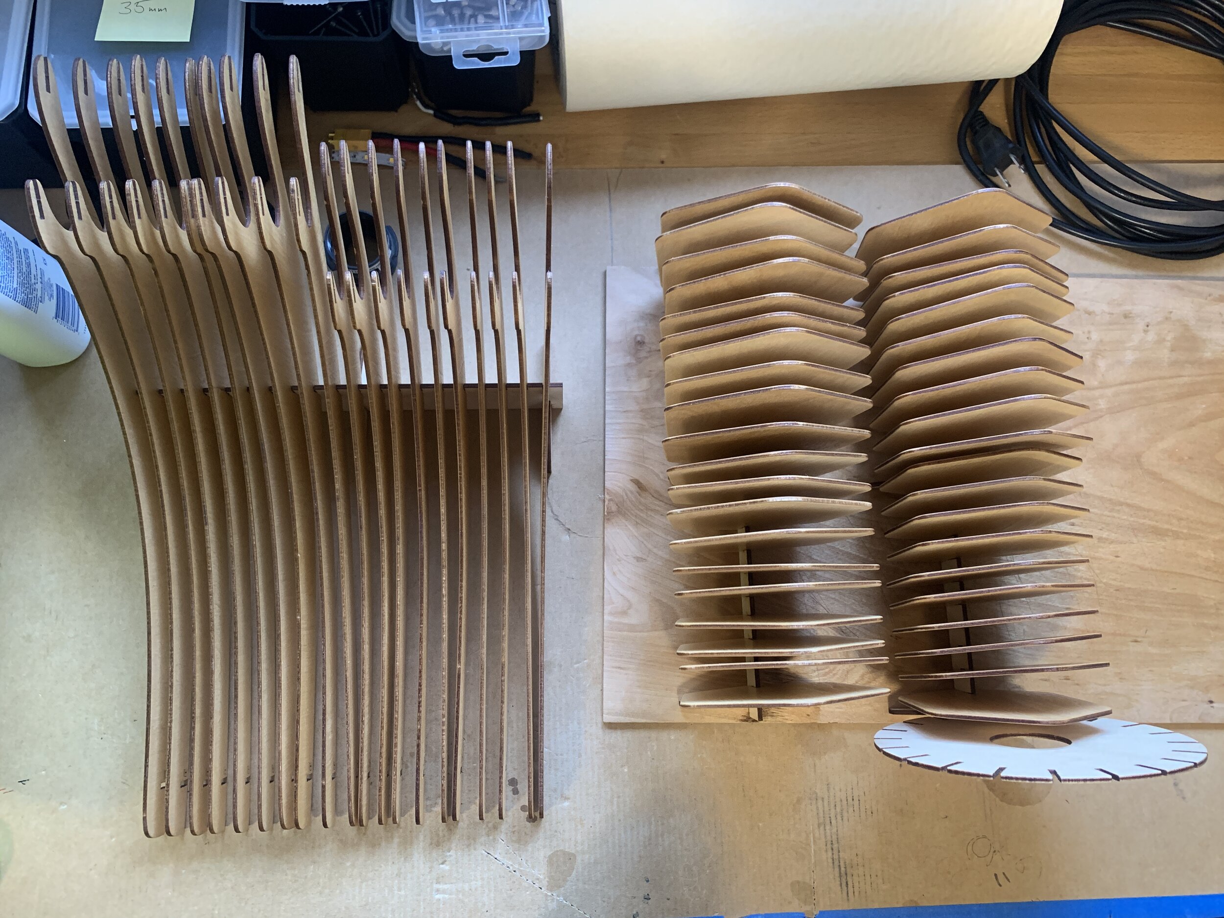
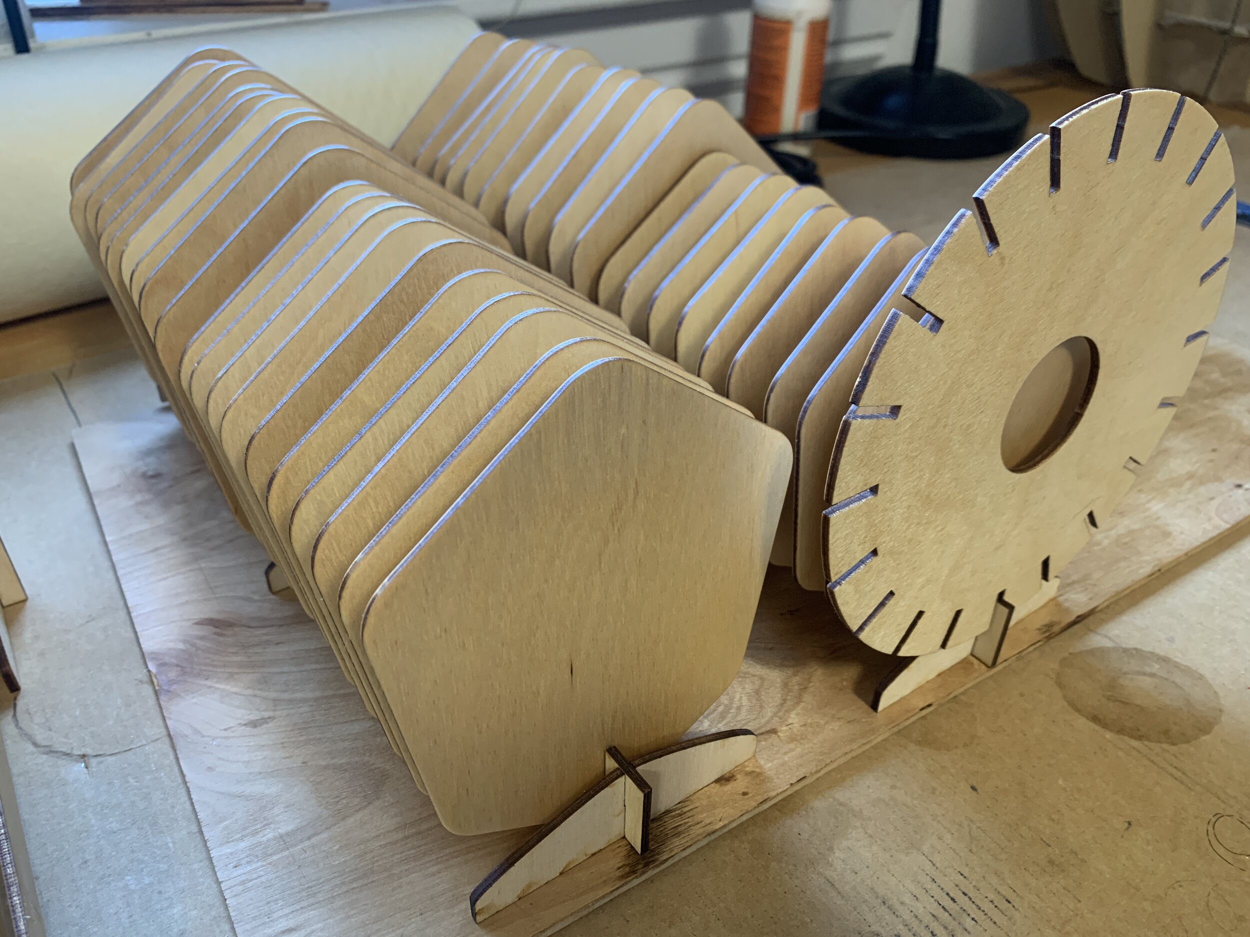
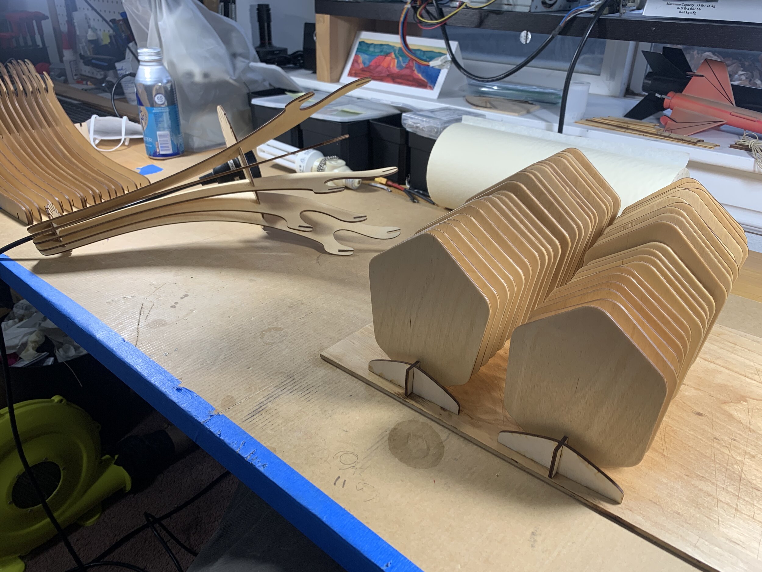
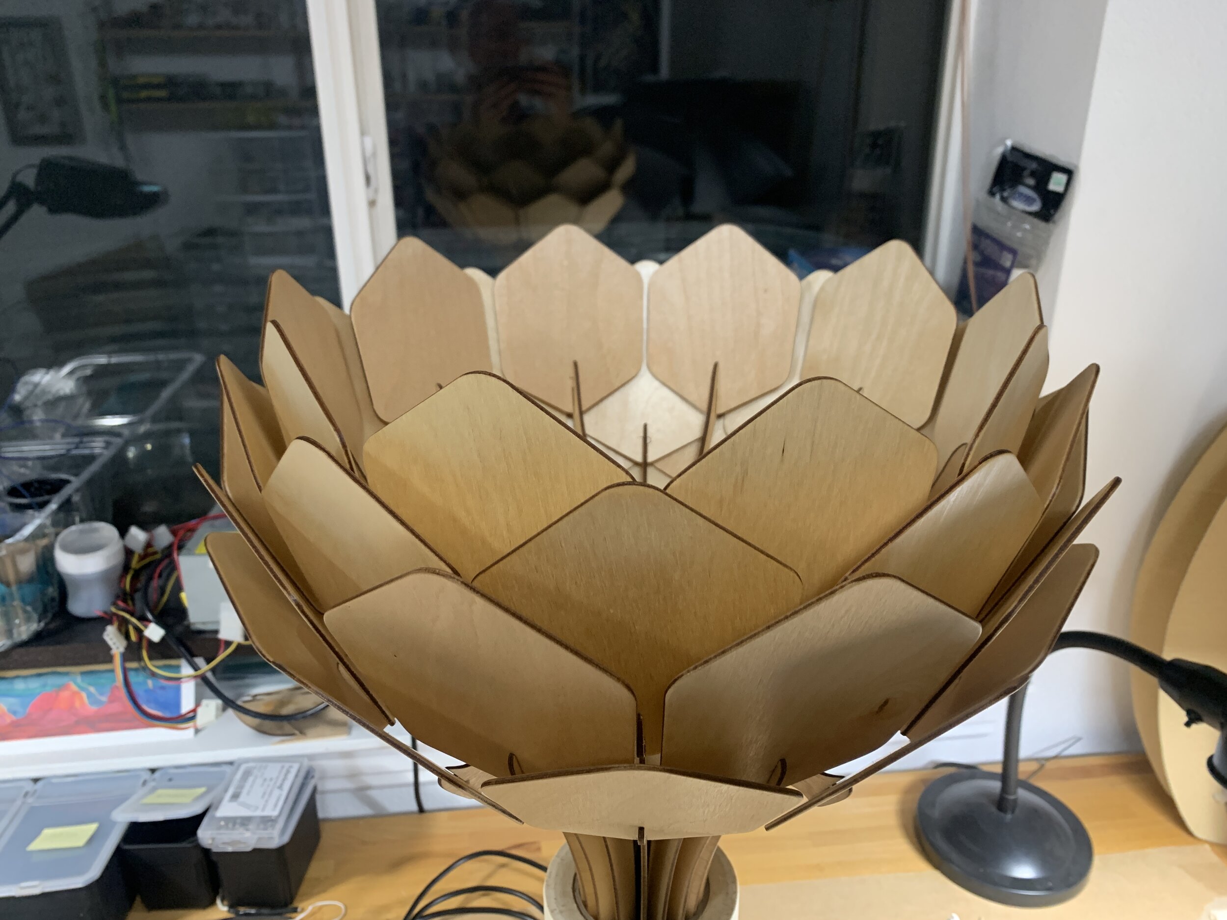
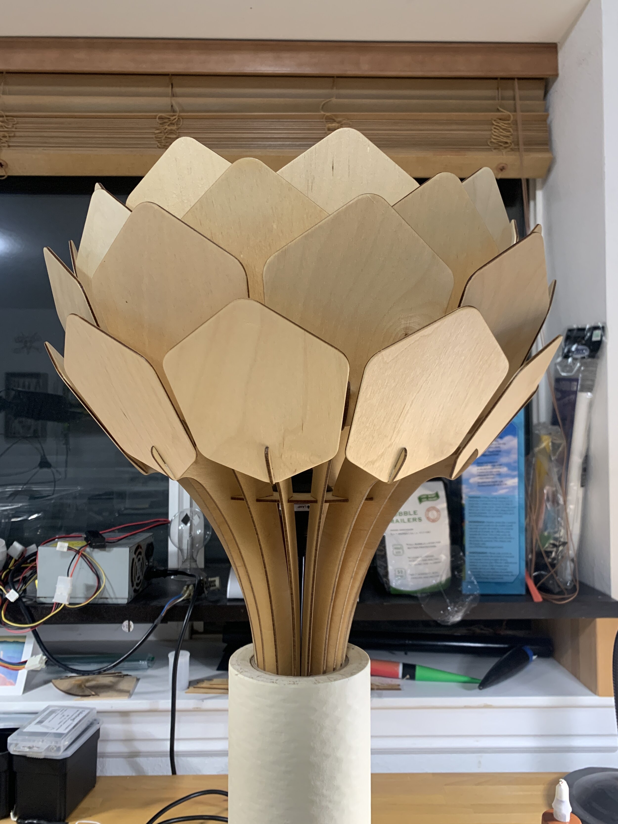
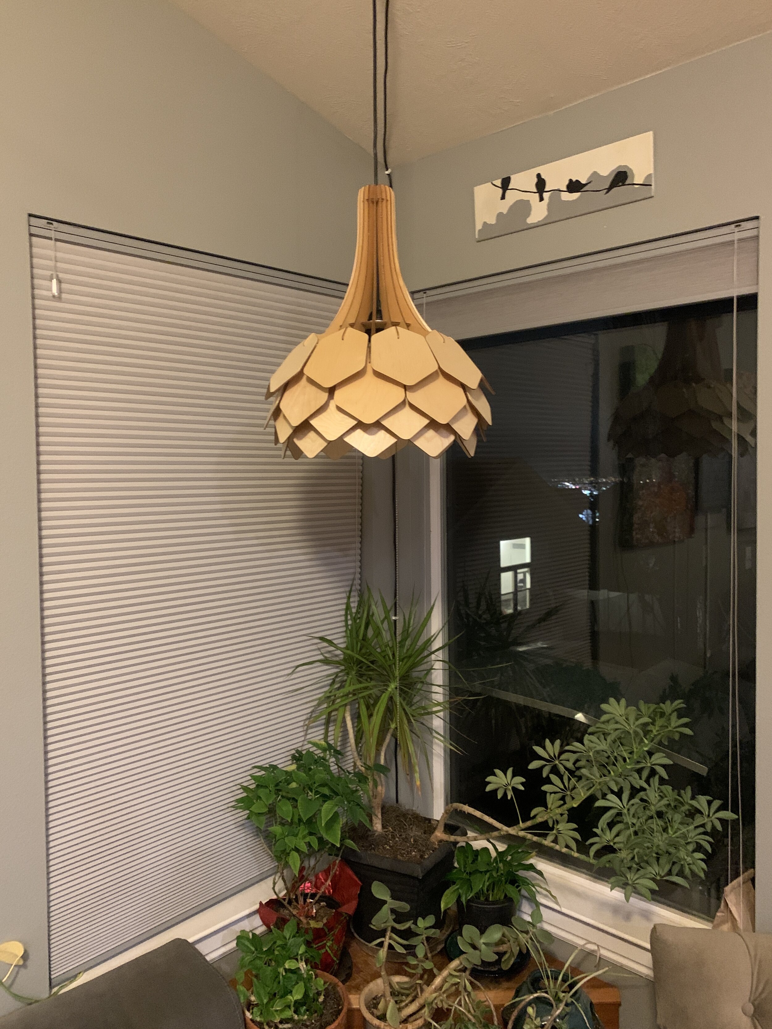
I used the standard 3mm / 1/8” 3 ply birch wood. Cutting, sanding and finishing took a few days. I finished it with Waterlox Original Sealer and Finish which is Tung Oil based. I made some quick drying racks for the parts to make handling them all easier. The pendant lamp cord bulb socket is something I had laying around but it’s similar to this one. Enough shop talk. Here’s some build photos and videos:
Geodesic Dome Build: 7 meter diameter 3V 5/9 Kruschke Type
TL;DR
The brief version for those who don’t want to read the full story:
It’s a 3V 5/9 Kruschke Type 7 meter (23 foot) diameter, 4.16m (13’-8”) tall Geodesic Dome that is made of 1 ⅜" outer diameter 16 Gauge (1/16" wall thickness) Galvanized Steel Pipe, of which 33 x 24’ lengths were used to cut 165 struts of 4 different lengths (30xA, 35xB, 80xC, 20xD) totalling 238.58m (782’-9”) of pipe and wasting 2.57m (8’-5”) of pipe. There are 61 strut connections/joints of 3 types (40x6-way, 6x5way, 15x4-way) that are made by flattening the ends of the struts and drilling 14mm (9/16”) holes 2.5cm (1”) from the end, then bolted together using 1/2”-13 x 1-1/2” long Zinc Hex Head Grade 5 Serrated Flange Bolts and 1/2”-13 Zinc Grade 5 Flanged Serrated Nuts, and one eye-nut with locking washer at the apex joint for hanging aerial equipment.
The total cost for the dome hardware itself was $883.63. When you add in the tooling I had to buy and other miscellaneous expenses, we spent a total of $1,167.17 to build the dome, plus another $235 to build a small retaining wall in the yard out of cinderblock. It took 5 adults and one child about 6 hours to build at a leisurely pace using two ladders, an impact driver with ¾” socket and an ¾” open ended wrench. The pre-build prep of the struts took MUCH longer.
Yes, you can climb all over it, it’s insanely sturdy. No, we aren’t going to cover it, but we might add some shade triangles in the future. I don’t know how much weight it can support, but it’d definitely more than I will ever have the capability of surpassing. I’m eventually planning to build a deck on top. We are already planning to bury a trampoline beneath it.
Here is the cleaned up version of the SPREADSHEET we used to keep track of all of this. It contains our calculations and a cost breakdown with links to items we purchased.
The Timelapse of the build is on YouTube and at the bottom of this post.
WHY?
Black Lotus Society sphere. Photo by Philippe Glade from his amazing This is Black Rock City Blog
With Burning Man 2020 cancelled, we decided we wanted to recreate a bit of the burn in our yard, and use the money we’d already paid for tickets to do so. The original idea was to replicate one of our favorite “domes” from a Burning Man 2017, the Black Lotus Society Camp’s, which was actually a nearly complete 24’ diameter 3V sphere with in the round seating, a trampoline, and aerial apparatus as. (You can read more details about it in this Reddit Post from one of the builders.)
The Vünderbar - photo from Torrey Smith
We quickly realized that despite having the footprint space for this sphere, we’d have no room to guy it down, which would be a definite requirement for stability and to keep it from rolling into our neighbors yard. So… back to the dome, nix the sphere.
I’ve wanted to build a deck that would allow us to see over our neighbor’s houses and into the SLC valley for many years, but the cost and permits cut that short every time I think of it. So that desire combined with confinement to dome land instead of a sphere reminded us of another amazing Burning Man dome… the Sextant Camp Vünderbar with Crow’s Nest and Zipline built by Torrey Smith and crew. (You can read more about their build in this thread on ePlaya.)
Now we’re talking. So I started digging back into all of the research I’d done on geodesic domes over the years to decide which type and size and sort the specs of what we could fit.
SPECS
I wanted it to be as tall as possible to fit within our space of about a 25’ x 25’ area. It needed to be strong enough to hang aerial equipment, climb all over, and support a deck on top. It needed to be deconstructable and reasonably easy to transport should we ever want to bring it to the playa. It also had to fit within our budget of two Burning Man tickets and a car pass, which for this year was around $1200 after fees and tax.
All of that narrowed me down to a 3V Geodesic Dome made of steel conduit. 3V references the “frequency” of the dome, and 3V is kind of a sweet spot for this type of build.
NOTE ON FREQUENCY: Most domes are based on Icosahedrons, which are 20 sided Platonic Solids made of equilateral triangles, which means all of it's side lengths are equal. That's a 1V frequency. If you break each side into two pieces, that's 2V and it now has two different lengths of sides. 3V, split the equilateral triangles into 3, and you now have a structure with 3 different side lengths. The higher the frequency, the closer you get to a sphere, the more sides lengths you have, and the more complexity. Check out Zip Tie Dome's write up for more details and illustrations of what Frequency is!
The problem with 3V domes (and all odd frequency domes) is that they don’t have a flat base. Even frequency spheres (2V, 4V, etc.) can be split at the equator and be flat, making a perfect dome base. So I thought about going up to a 4V dome, but the increase in cost and complexity wasn’t worth it (you go from 165 struts to 250 struts for one thing). To the rescue comes the 3V 5/9 Kruschke Type dome, which is a specific derivation that allows you to take odd frequency domes and add one strut length in order to make a truncation that is slightly more than half the sphere (or less than half if you so choose) with a flat base … so that’s what I went with. The Domerama 3V 5/9 Flat Base Kruschke Calculator was the only one I could find that provided the calculations needed to make the flat base, so it was what we used to calculate our measurements. Highly recommend all of the calculators and exploring the entire Domerama site… lots of great info.
Given our space, we figured we could fit a 7 meter (23-ish foot), which would give us a 4.2 meter (13’-8”) tall dome. I put a ladder out, had Sarah hold a tape measure, climbed up and eyeballed 4.2 meters and could see over the neighbor’s house. Perfecto.

MATERIALS
Nearly every dome build I could find online says to use steel conduit because it’s cheap and readily available in the US, won’t rust easily, and is easy to squish to make the joint connections. It comes in 10’ lengths which is a magic number for maximizing cuts and minimizing waste for certain size domes, which I’ll get into later. Most say to use ¾” conduit, but that’s mostly for shade domes, and we want to be able to climb all over this thing remember, so I went to Home Depot and bought a 10’ length of 1” conduit, which is $9.28 each in bulk, to check it’s strength. We simulated the longest length of side/strut and hung from it and stood on it… and it was quickly evident that it was on the edge of acceptable… but would bend with not much weight in the middle of a strut. Conduit gets waaay more expensive when you go above 1”. This was a big bummer.
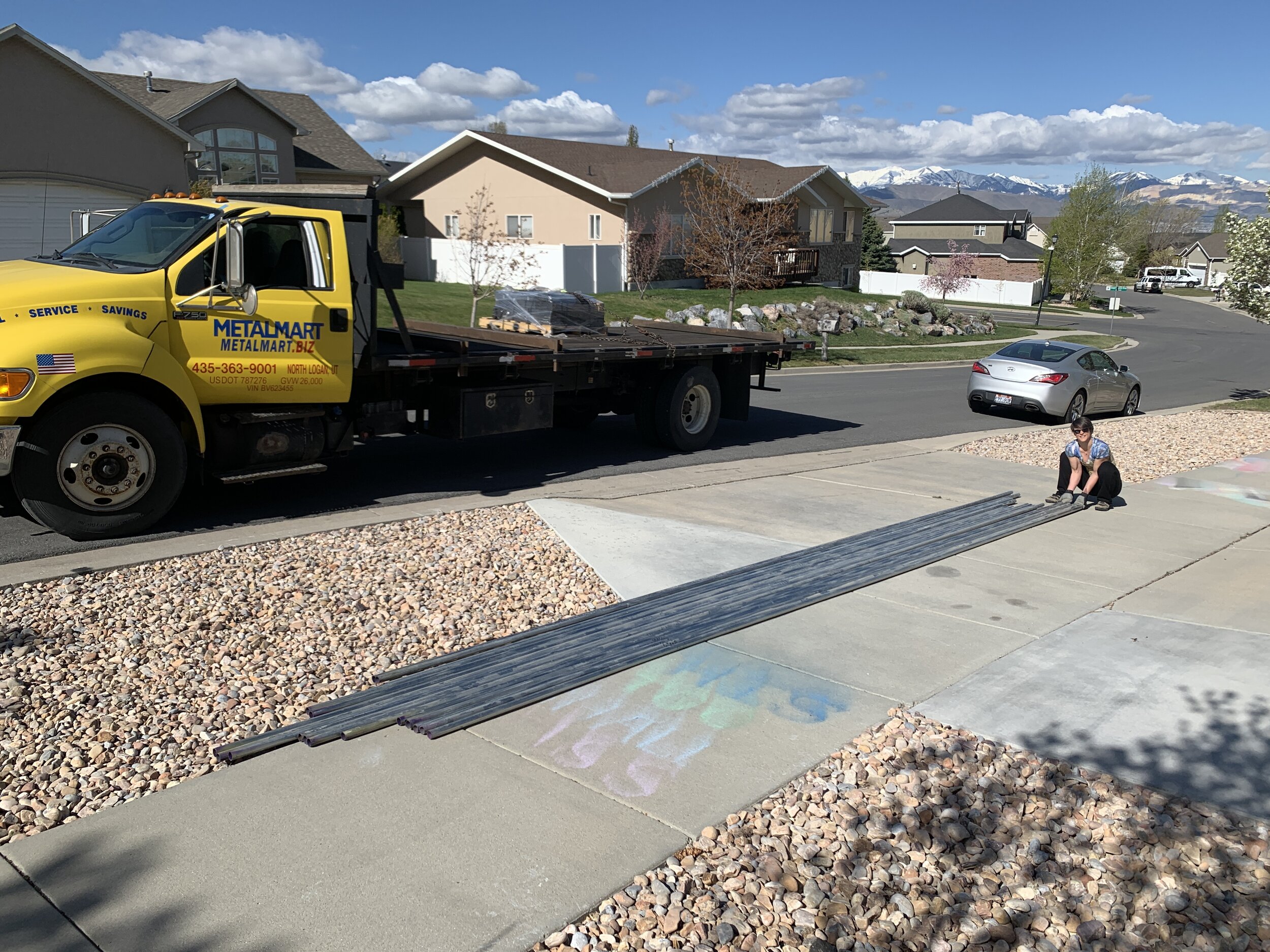
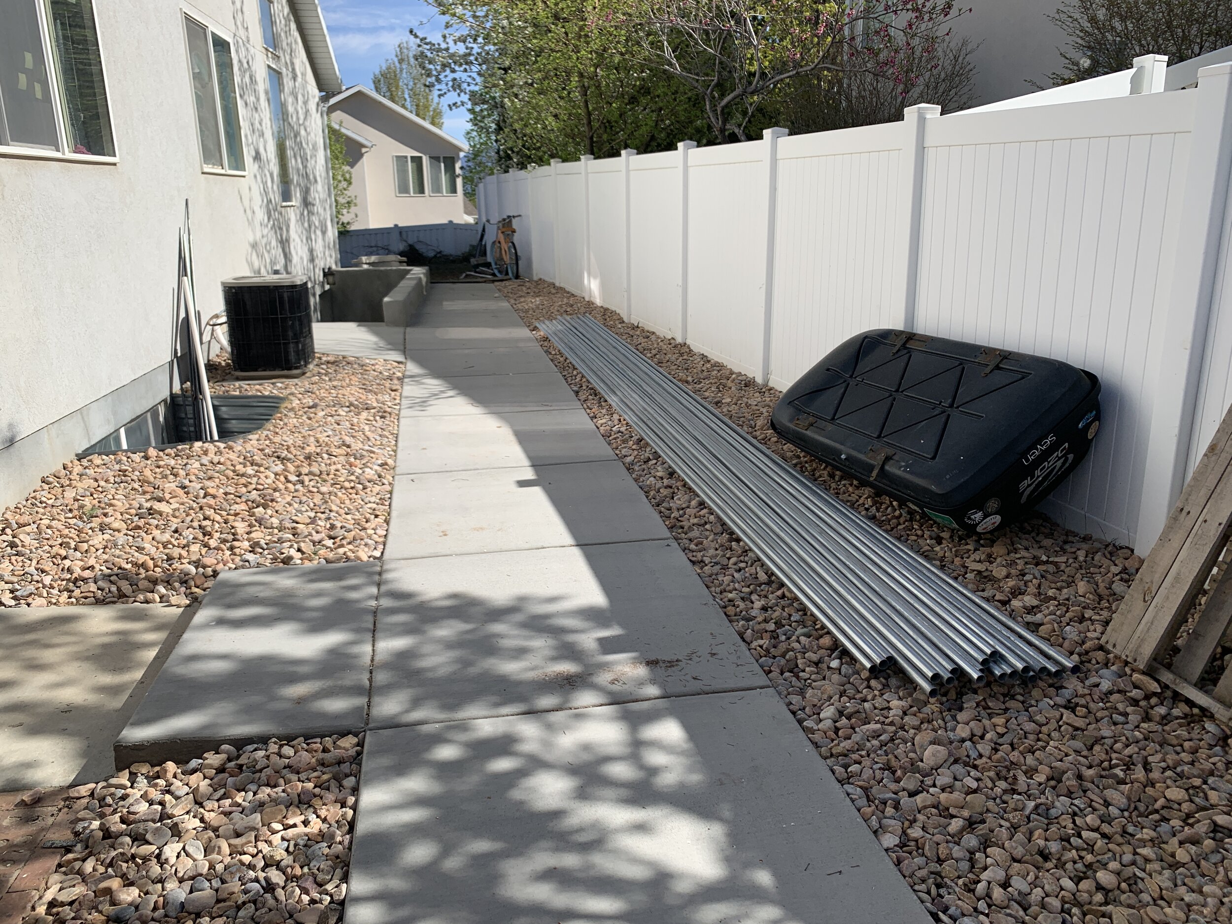
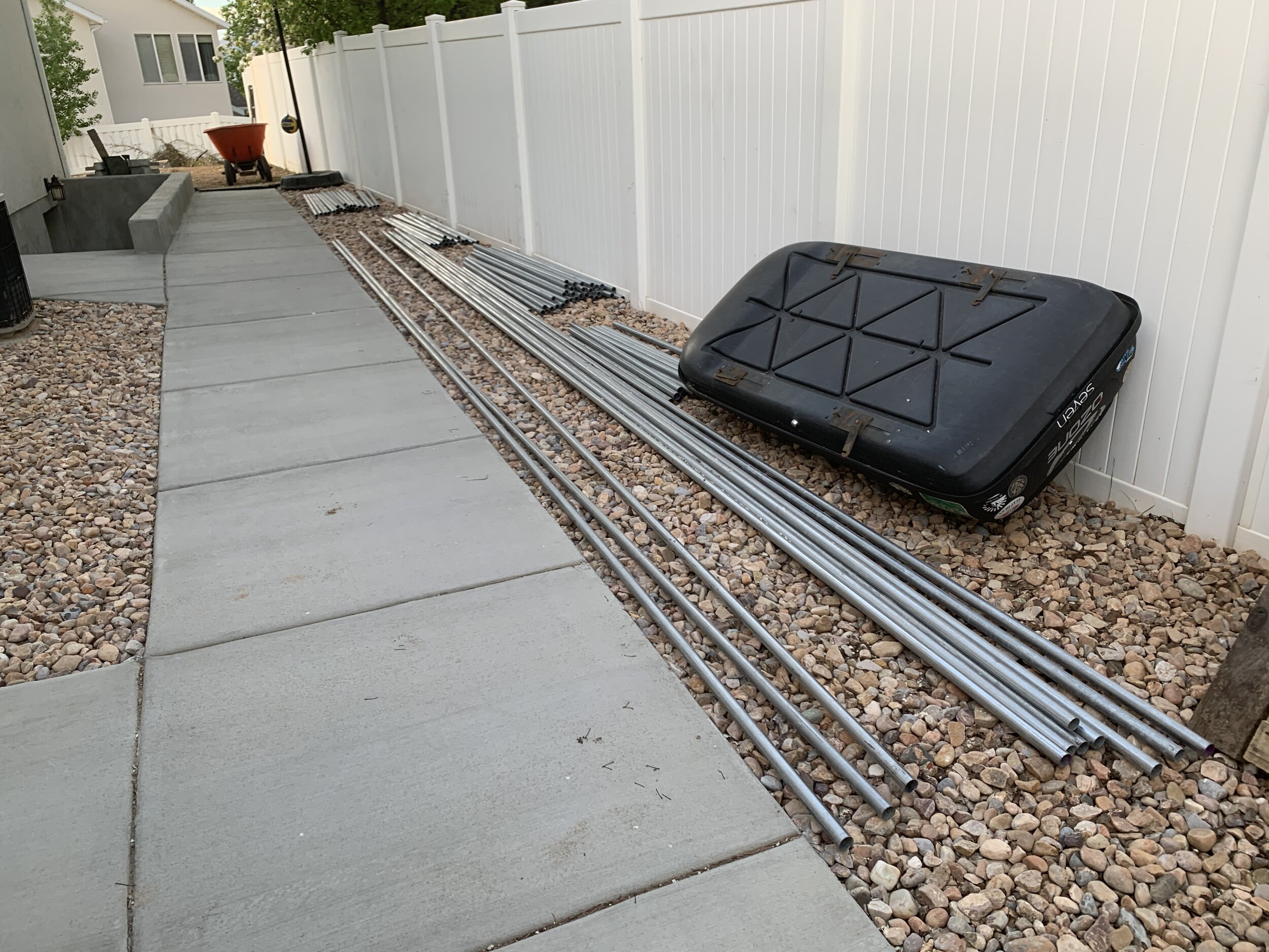
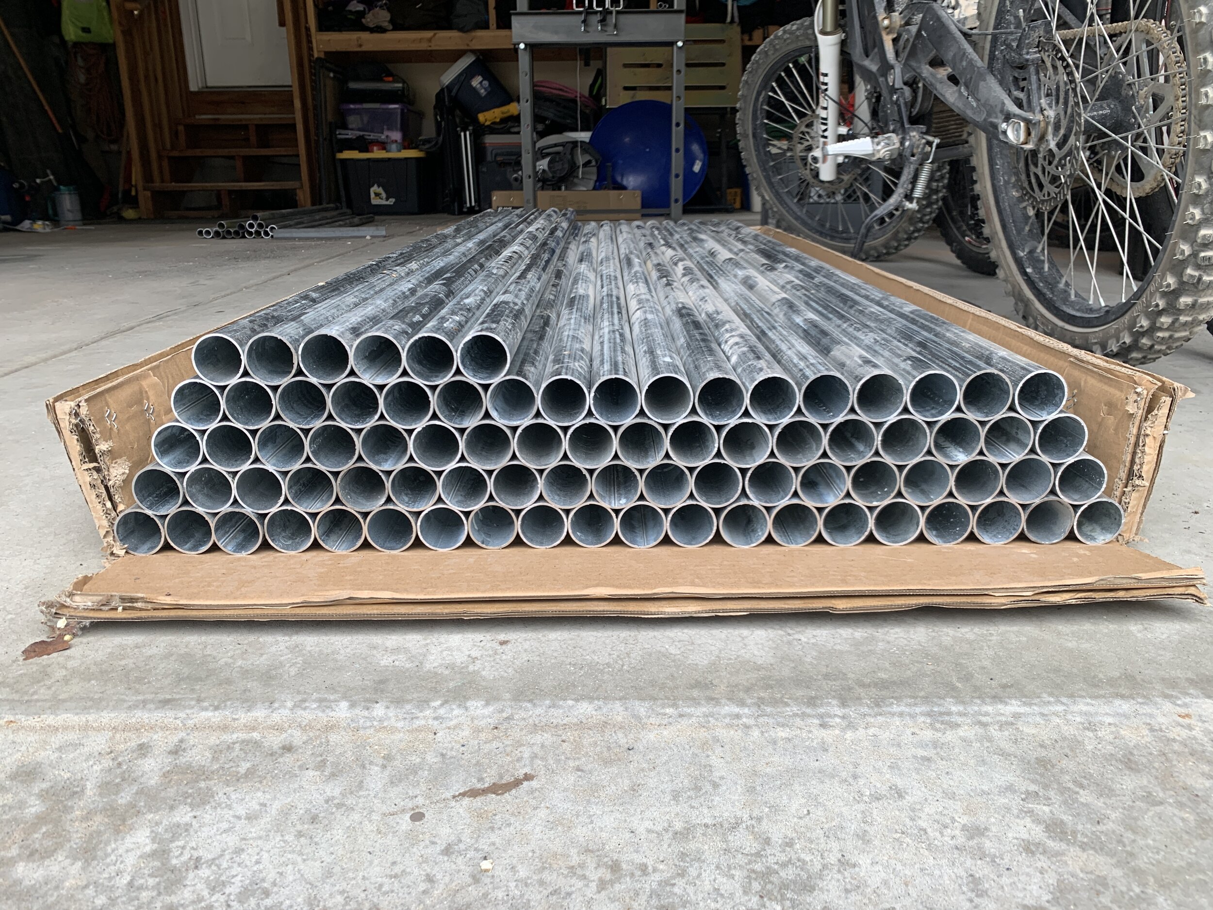
Out of curiosity I checked with a local place called MetalMart to see if they had conduit for cheaper than Home Depot, and they happened to have 24' Lengths of 1 ⅜" Outer Diameter 16 Gauge (1/16” wall thickness) Galvanized Pipe for $18.98 per length in bulk, which ended up being considerably cheaper than conduit, thicker, and stronger. SOLD. Sarah and I went and bought a length and had them cut it in half so I could get it home in the Honda Element. Immediately it was obvious this was the way to go. Now we just needed to make sure we could flatten the ends to make the joints.
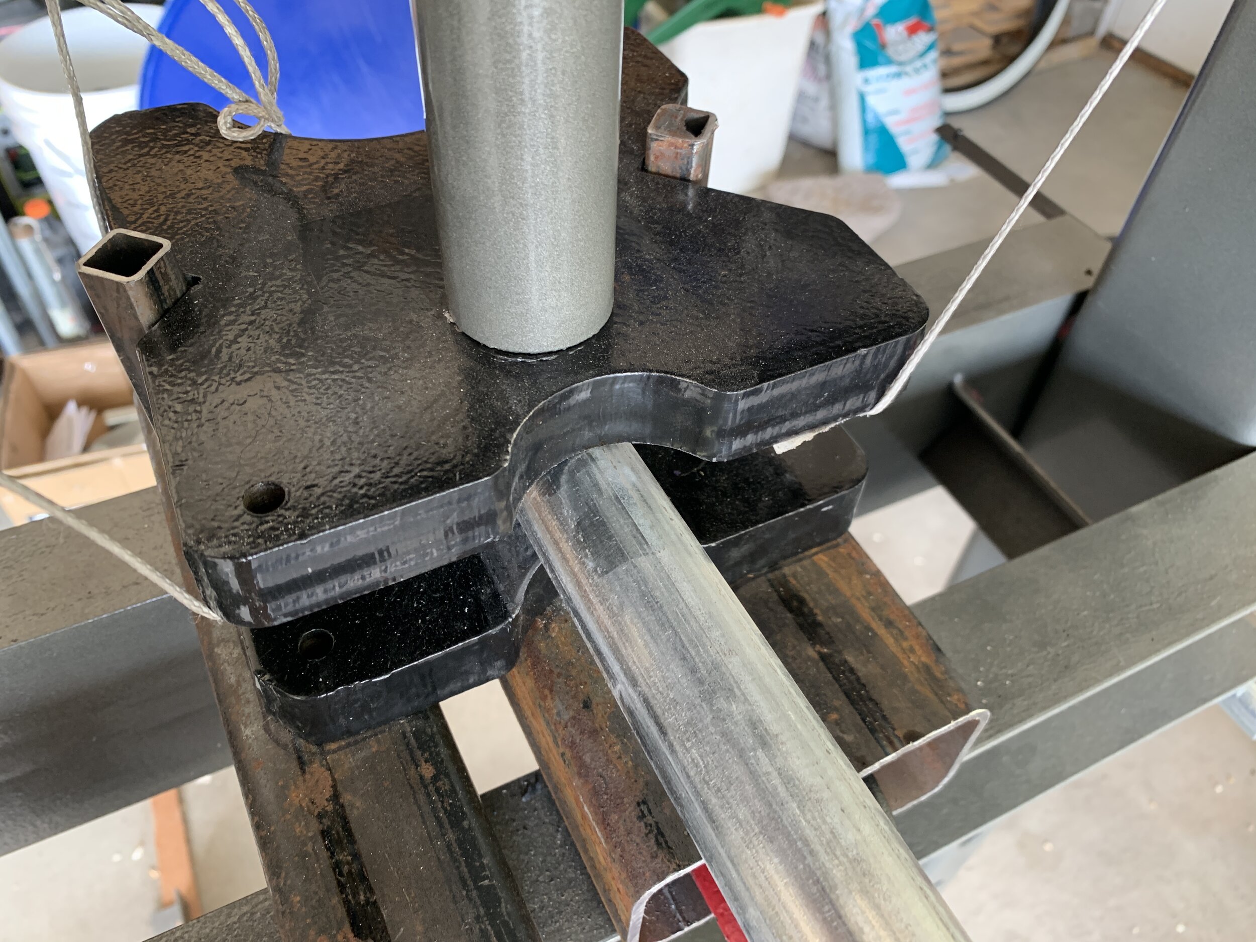
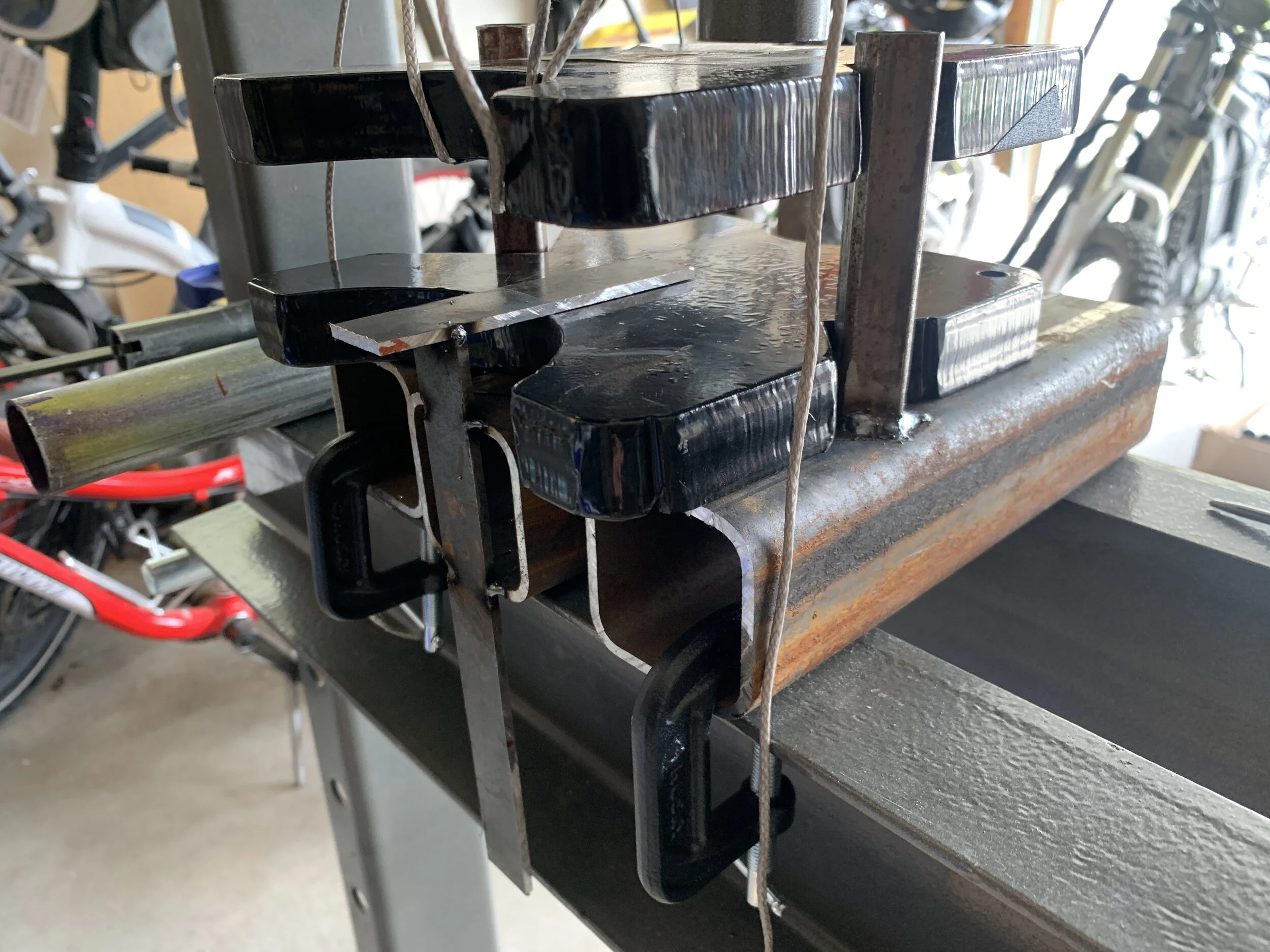
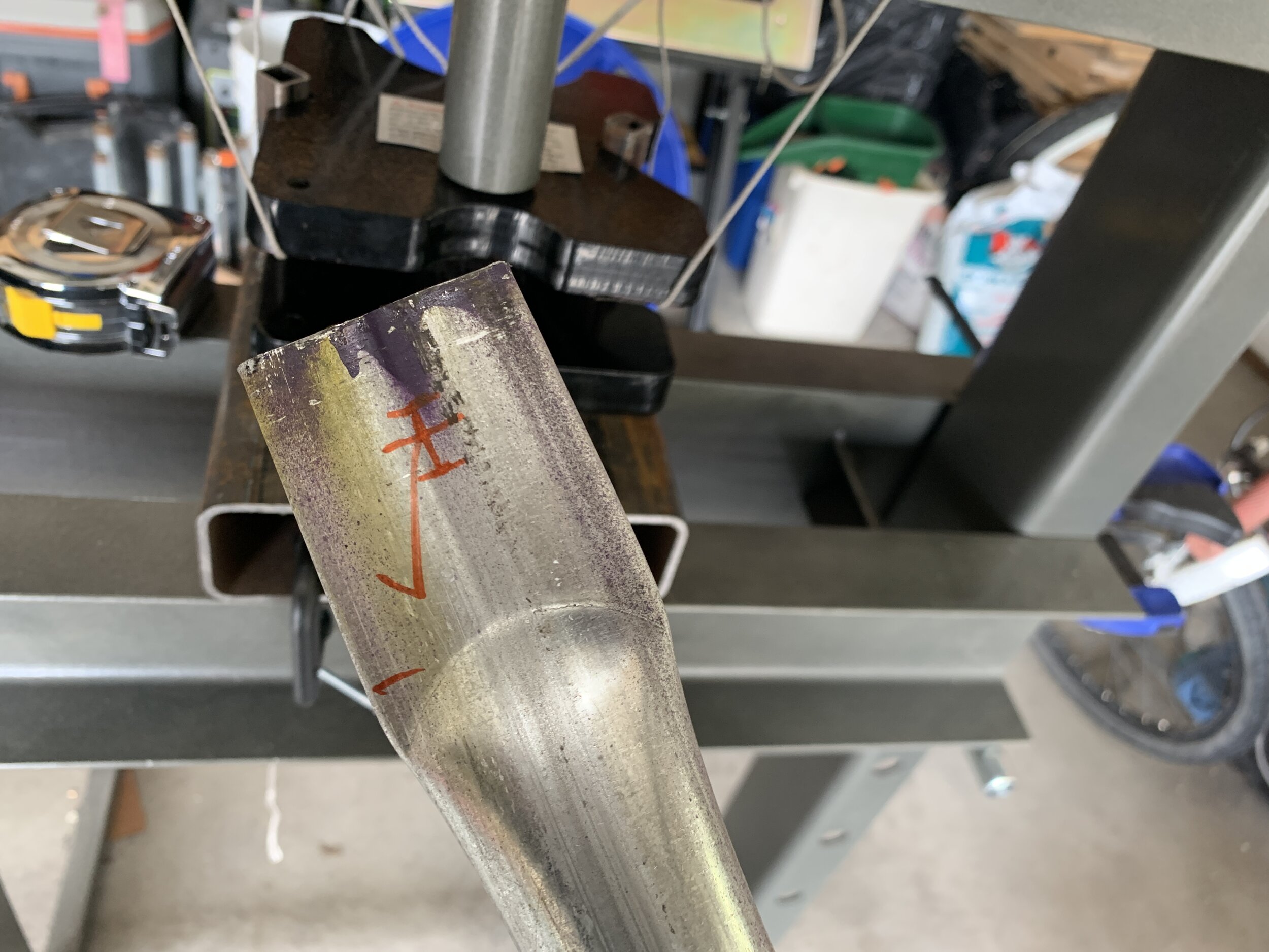
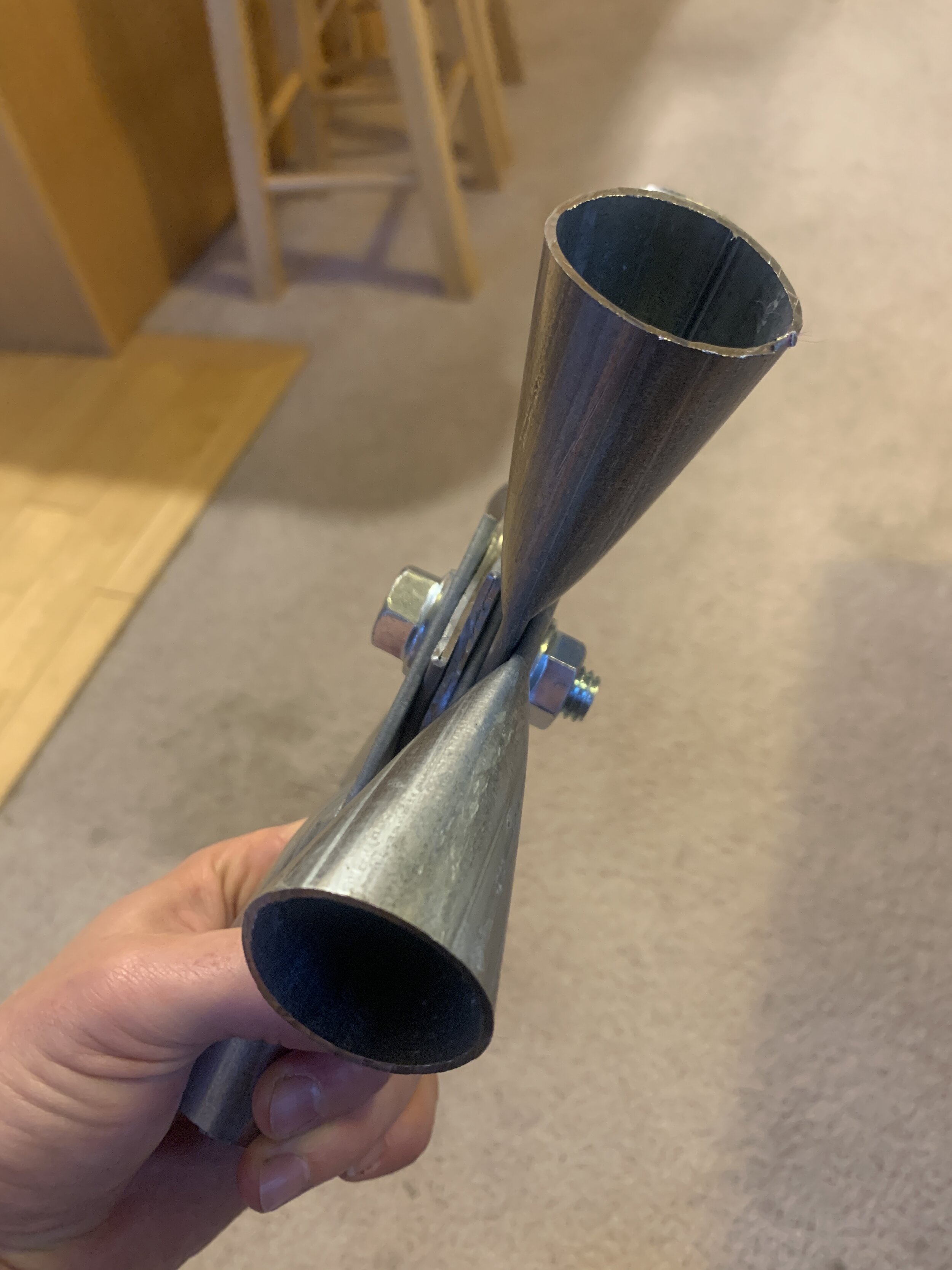
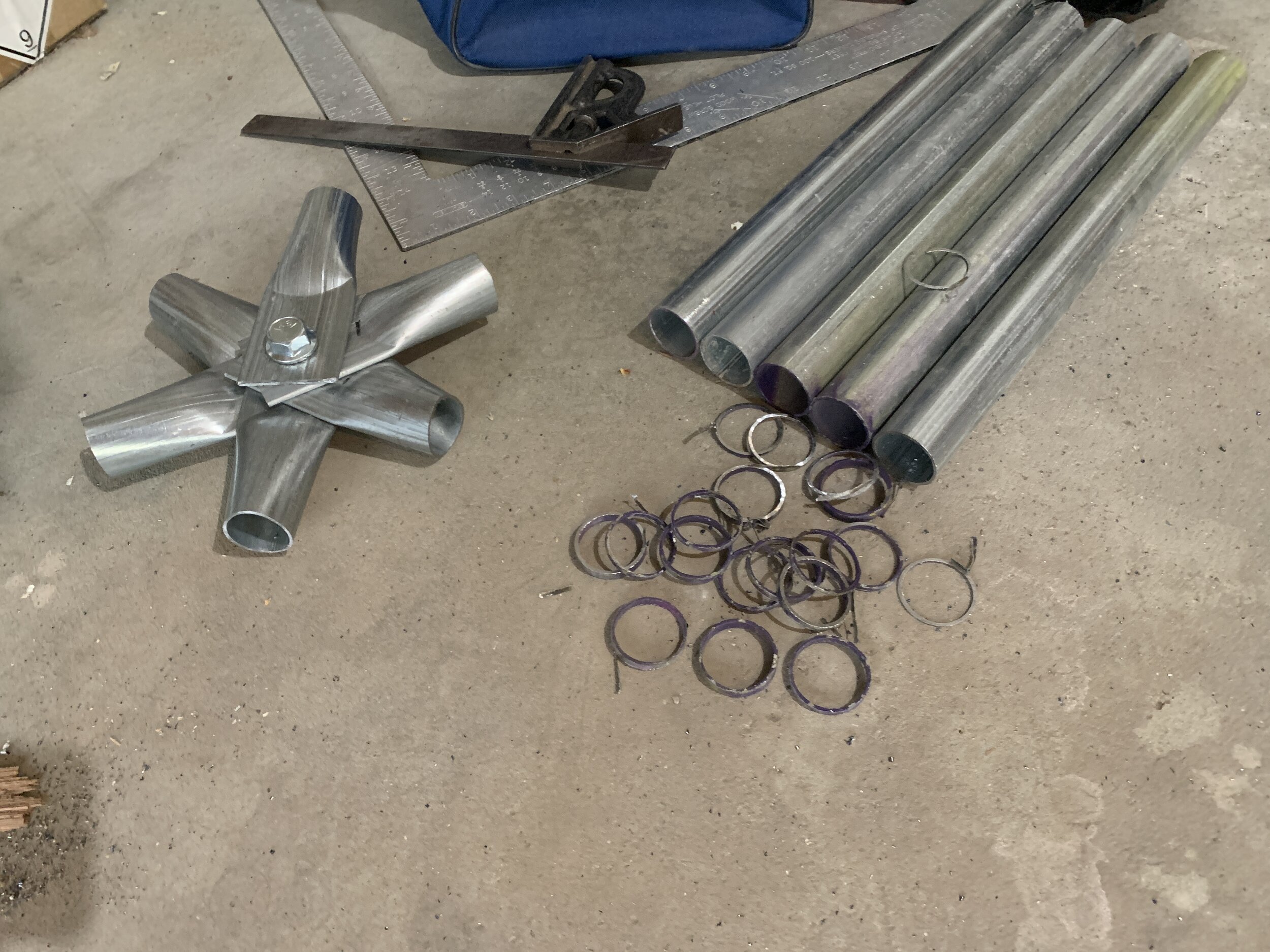
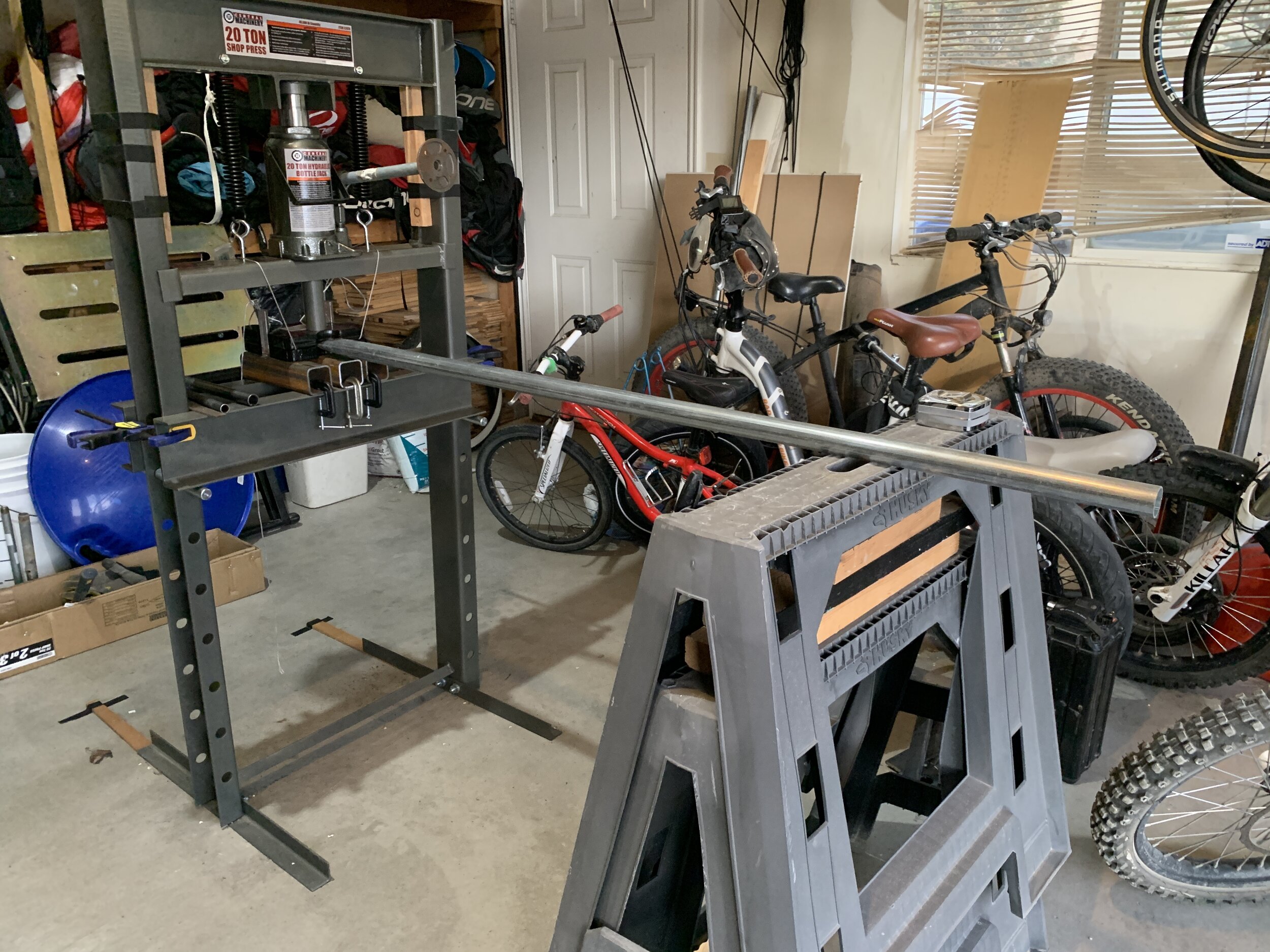
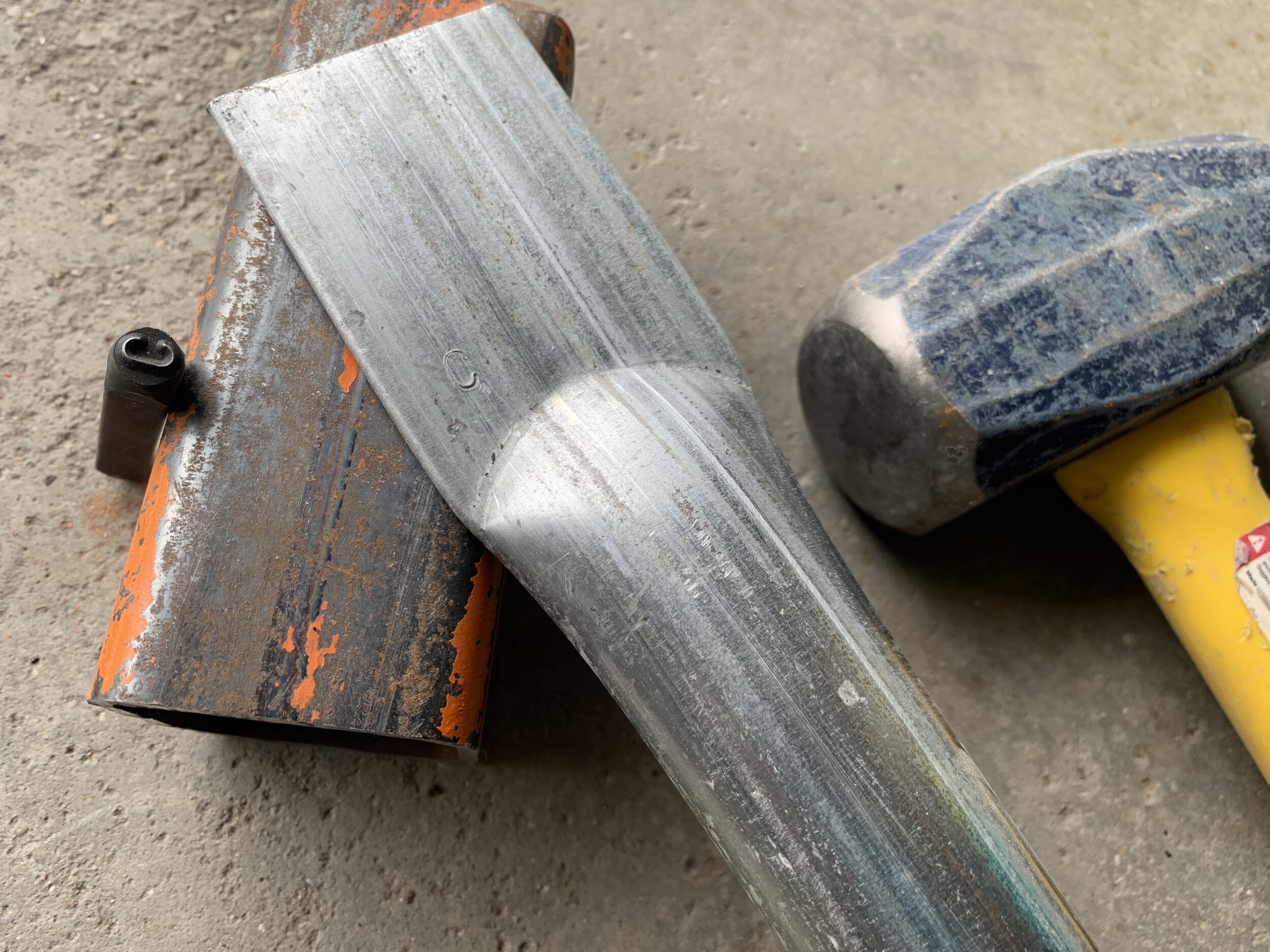
To join all the struts together, you squish the ends flat, and drill a hole in it so you can bolt them all together. I’d bought a 12 Ton Hydraulic Bottle Jack at Harbor Freight with plans to weld up a jig to do the flattening, but once I saw the 1 ⅜” pipe it was evident it wouldn’t cut it. So I returned that and got the 20 Ton H-Frame Industrial Heavy Duty Floor Shop Press on sale for $150 instead. We cut a few test pieces and gave it a go… It worked very well.
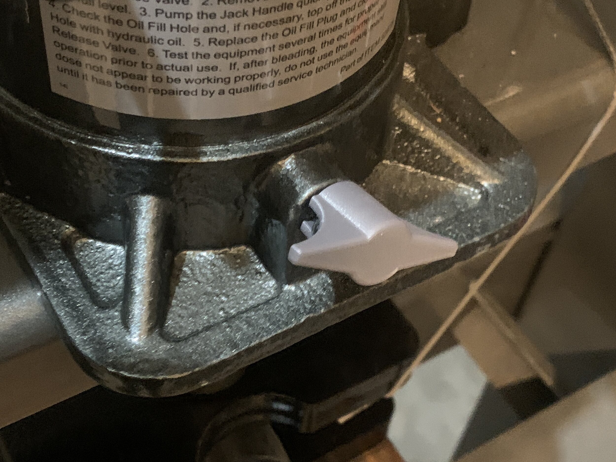
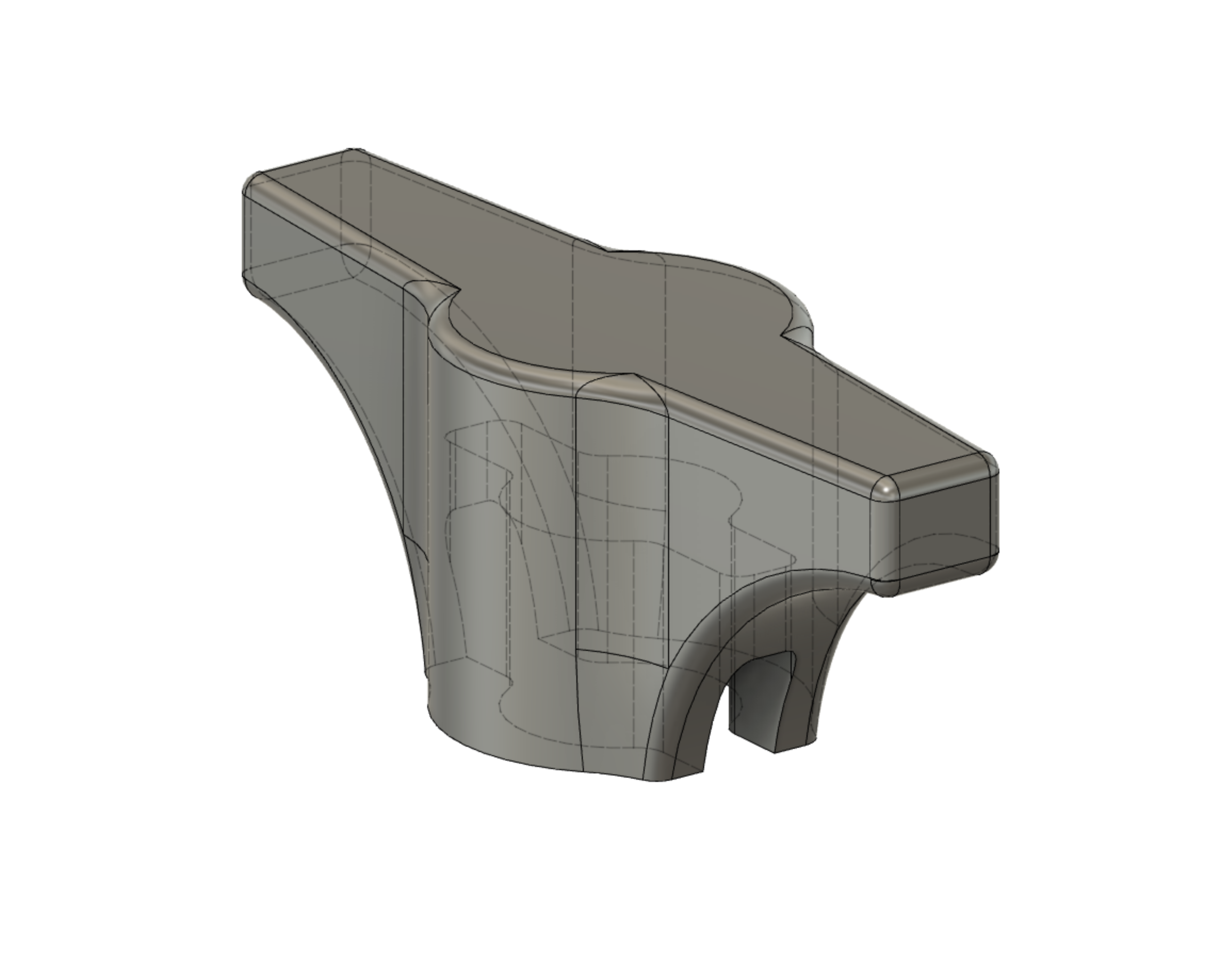
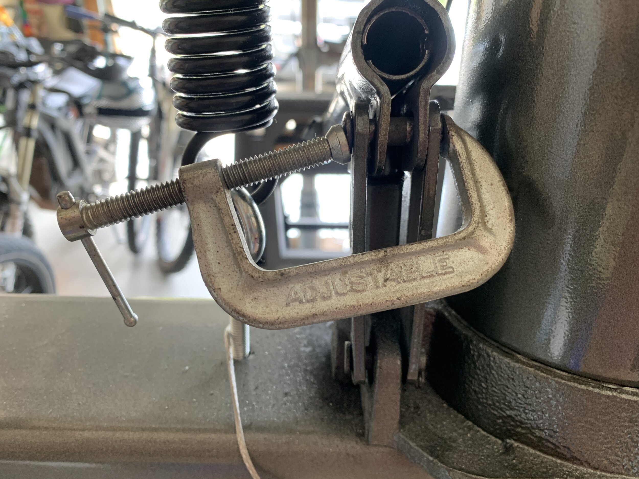
The arbor plates the press comes with happen to have the perfect curvature for pressing the ends of the pipe. I’ve read numerous places that it’s important to make the pressed edge have a radius for strength instead of making it straight, so this was perfect. I quickly welded up a jig with some square tube so that the top plate and bottom plate would stay aligned. I added a stop made of bar steel that was the same thickness as the flattened pipe (1/8”) so you could quickly insert the pipe and get consistent size flattened ends. We also tied the top plate so it would be lifted by the cross beam of the press to make it easy to put the pipes in and out. Everything was clamped down with C-clamps so things could be adjusted when they eventually got out of spec from all the pressure, which it did a couple times. We also had to add shims to the cross bar of the floor press to keep it from going up at an angle at times, and had to clamp the base cross bar to the frame so that it didn’t move under pressure. This is Harbor Freight, these things are to be expected. I also modeled and 3D printed a knob (Fusion 3D file, STL file) for the hydraulic release on the 20-ton bottle jack so we didn’t have to keep pulling the crank pipe out to turn and release pressure.
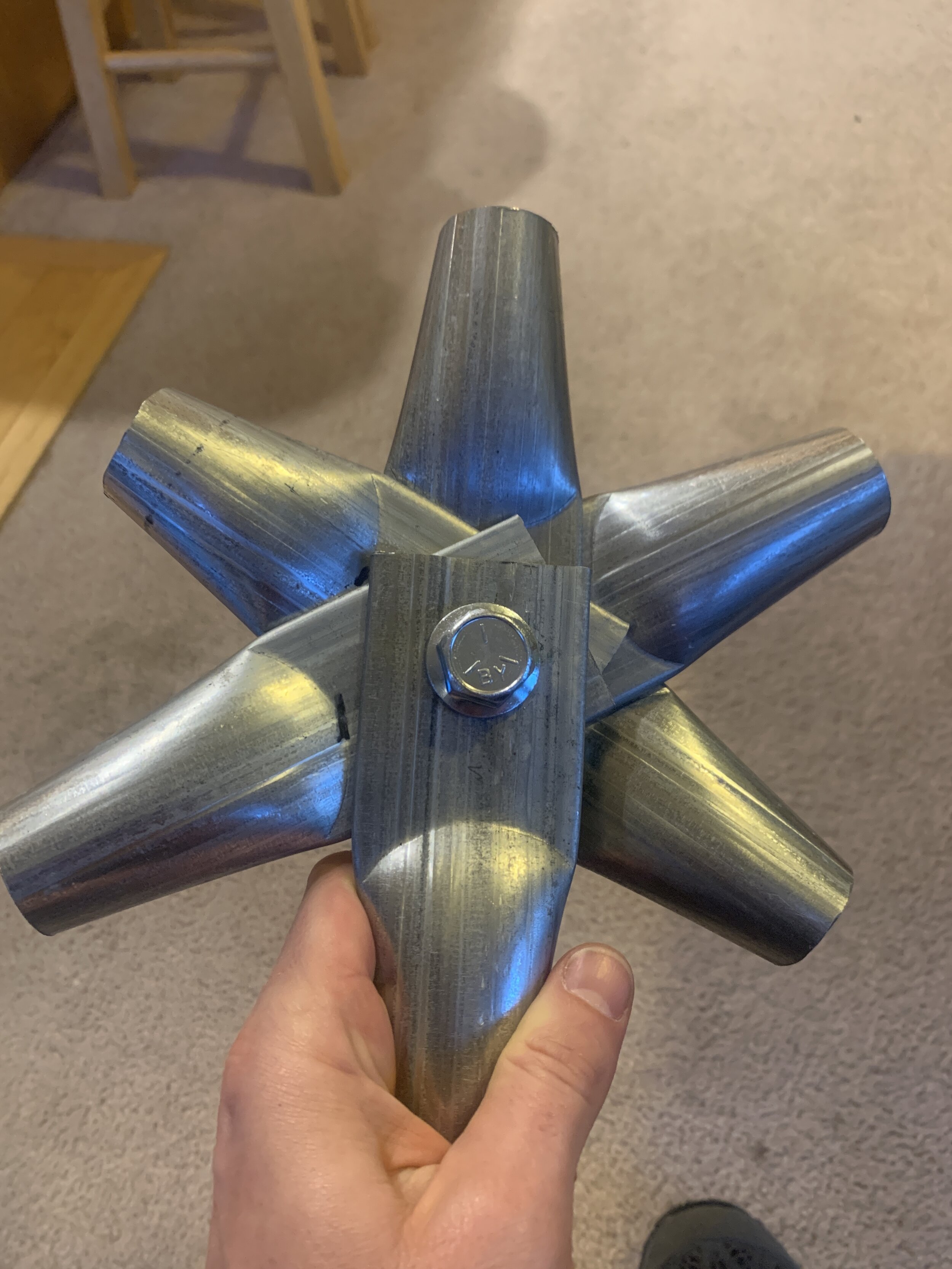
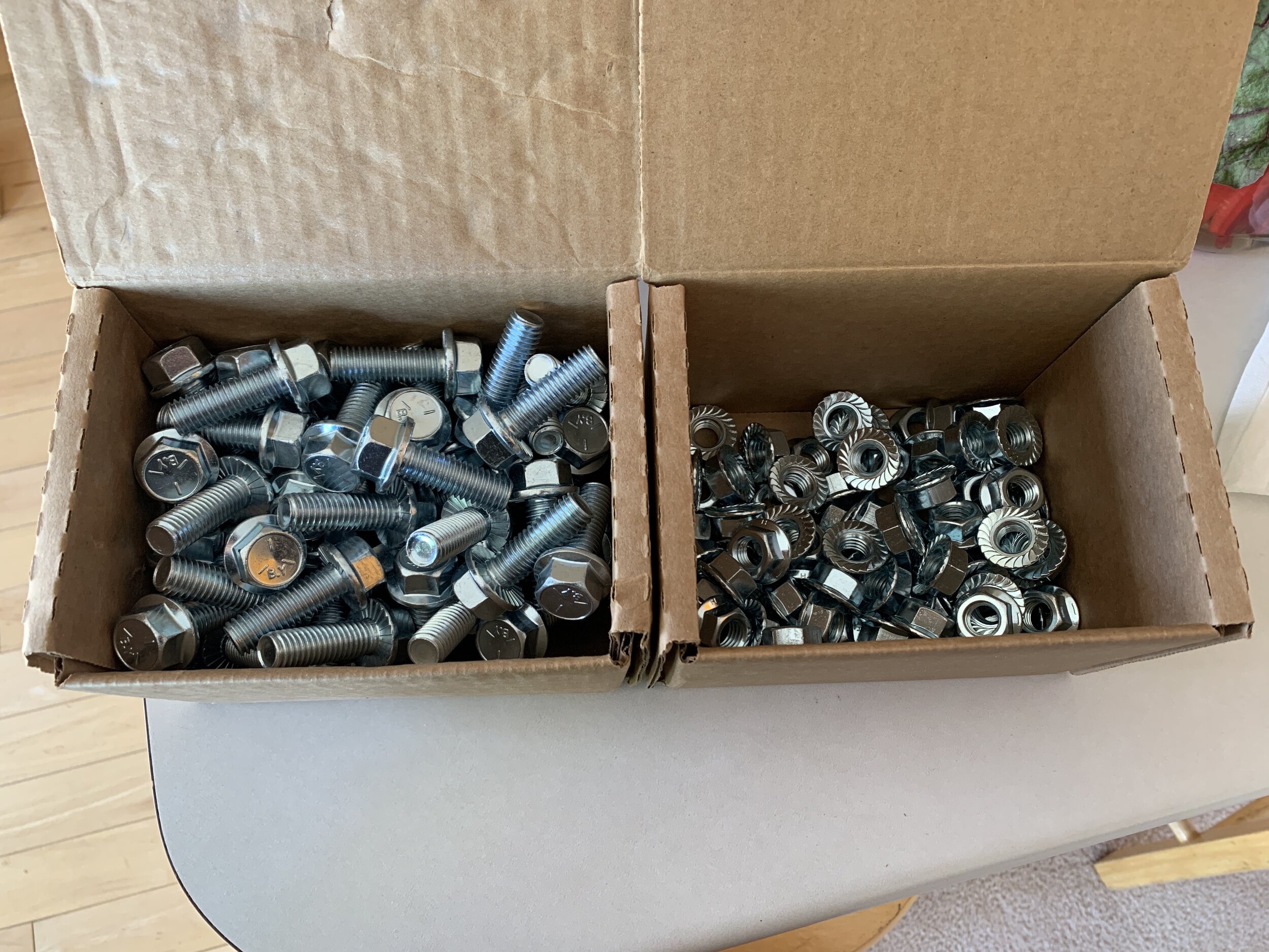
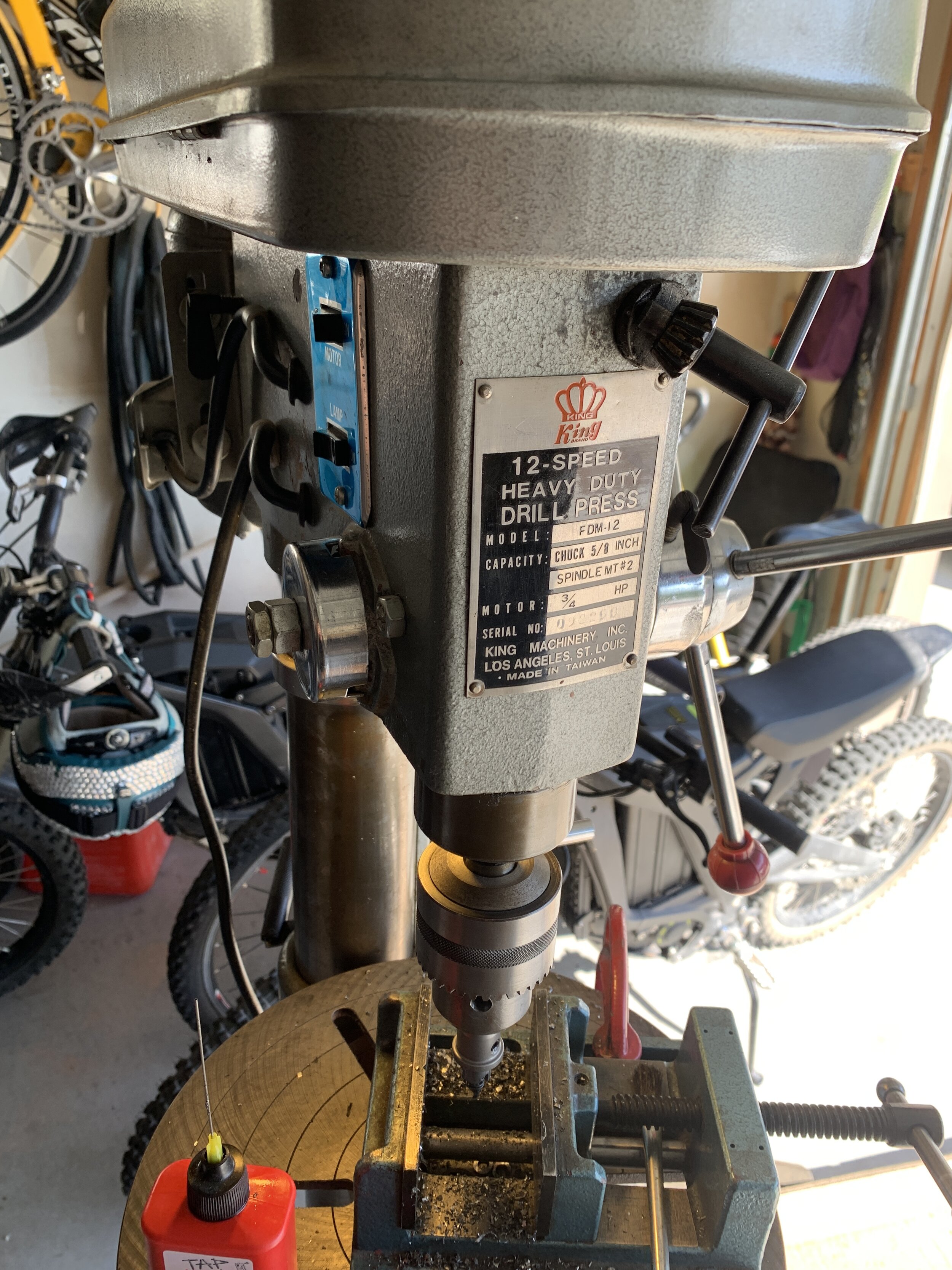
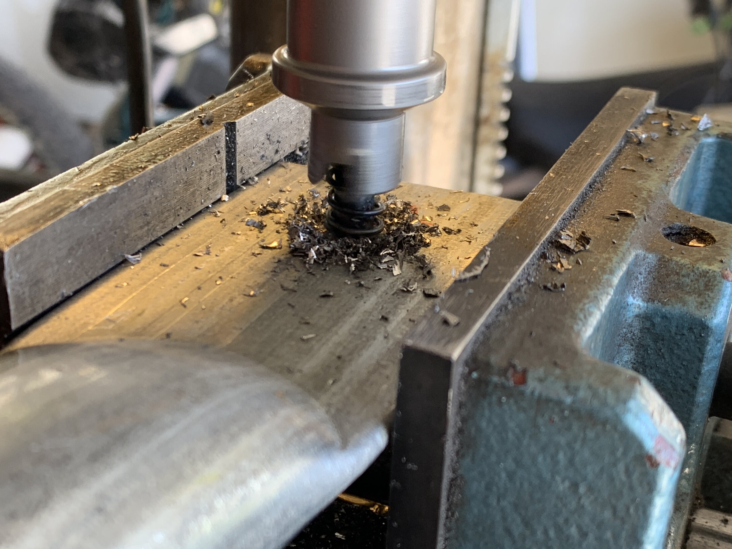
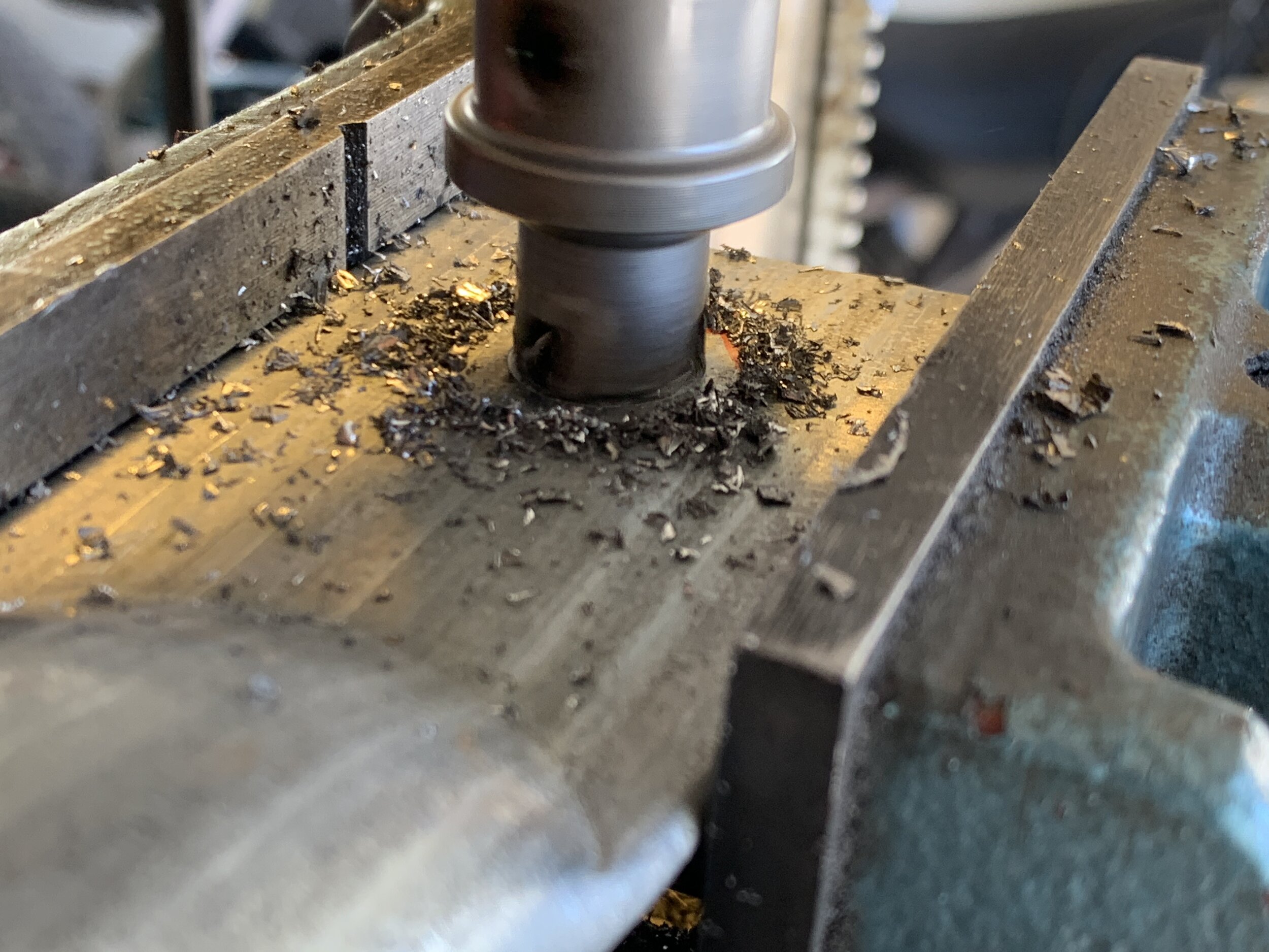
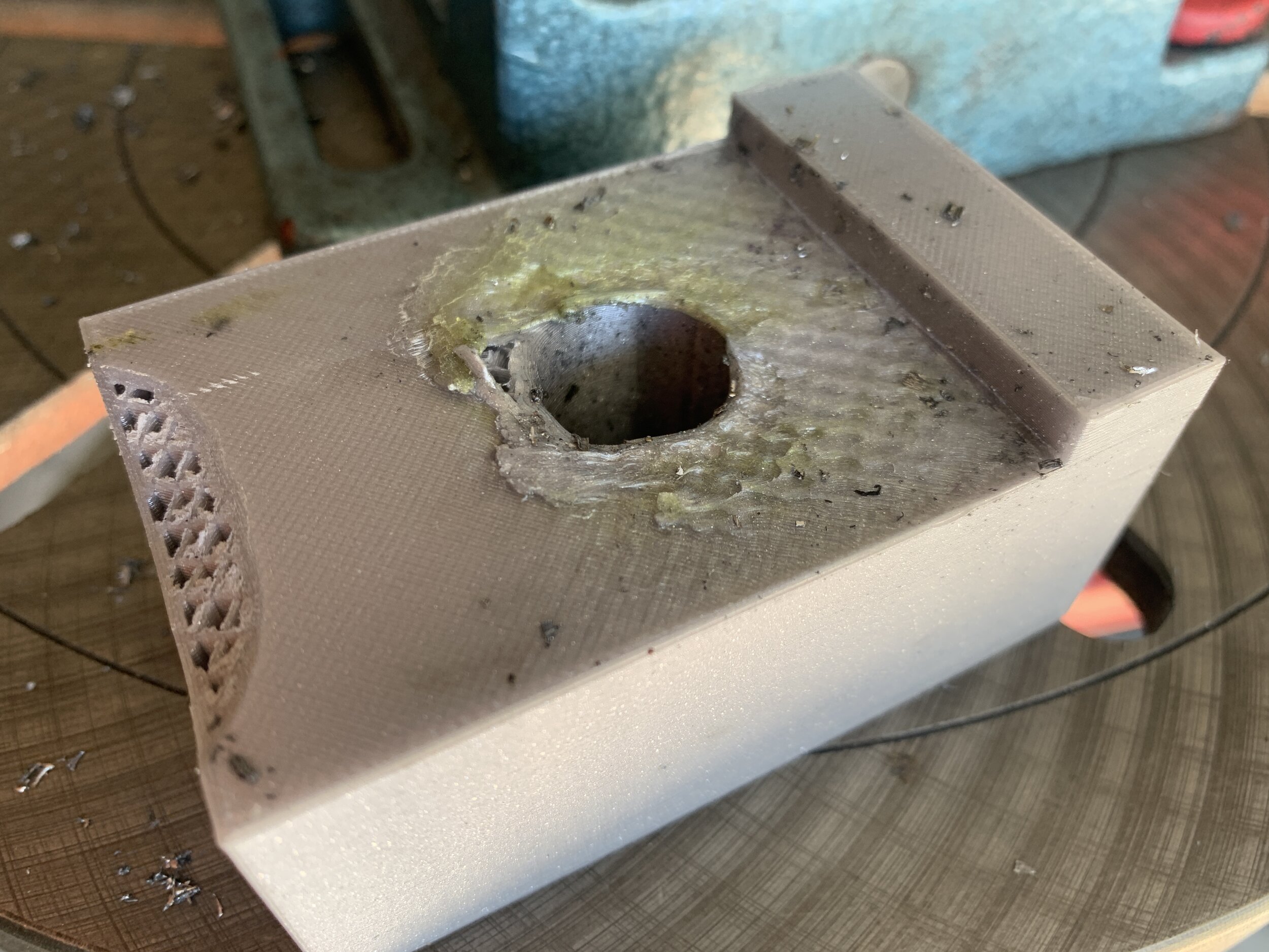
I decided that we should flatten 6cm (2.5”) of the end of each pipe, and drill the holes at 2.5cm (1”) from the end. I then built a quick joint test thanks to Dave Chapman’s drill press to check the flattening size and confirm bolt length. Since each end is about 3.3mm (⅛”) thick when flattened, when 6 ends are stacked (the most common joint for this dome as there are 40x6-way, 6x5way, and 15x4-way joints) you have about 20mm (¾”) to bolt through, so I landed on drilling 14mm (9/16”) holes and using 1/2”-13 x 1-1/2” long Zinc Hex Head Grade 5 Serrated Flange Bolts and 1/2”-13 Zinc Grade 5 Flanged Serrated Nuts to secure the joints. Serrated flange bolts and nuts mean no fumbling with washers when bolting it all together. Boltdepot.com had the best prices and services I could find. I also ordered a forged eye nut and Nord-lock washer to put at the apex joint to hang aerial equipment from.
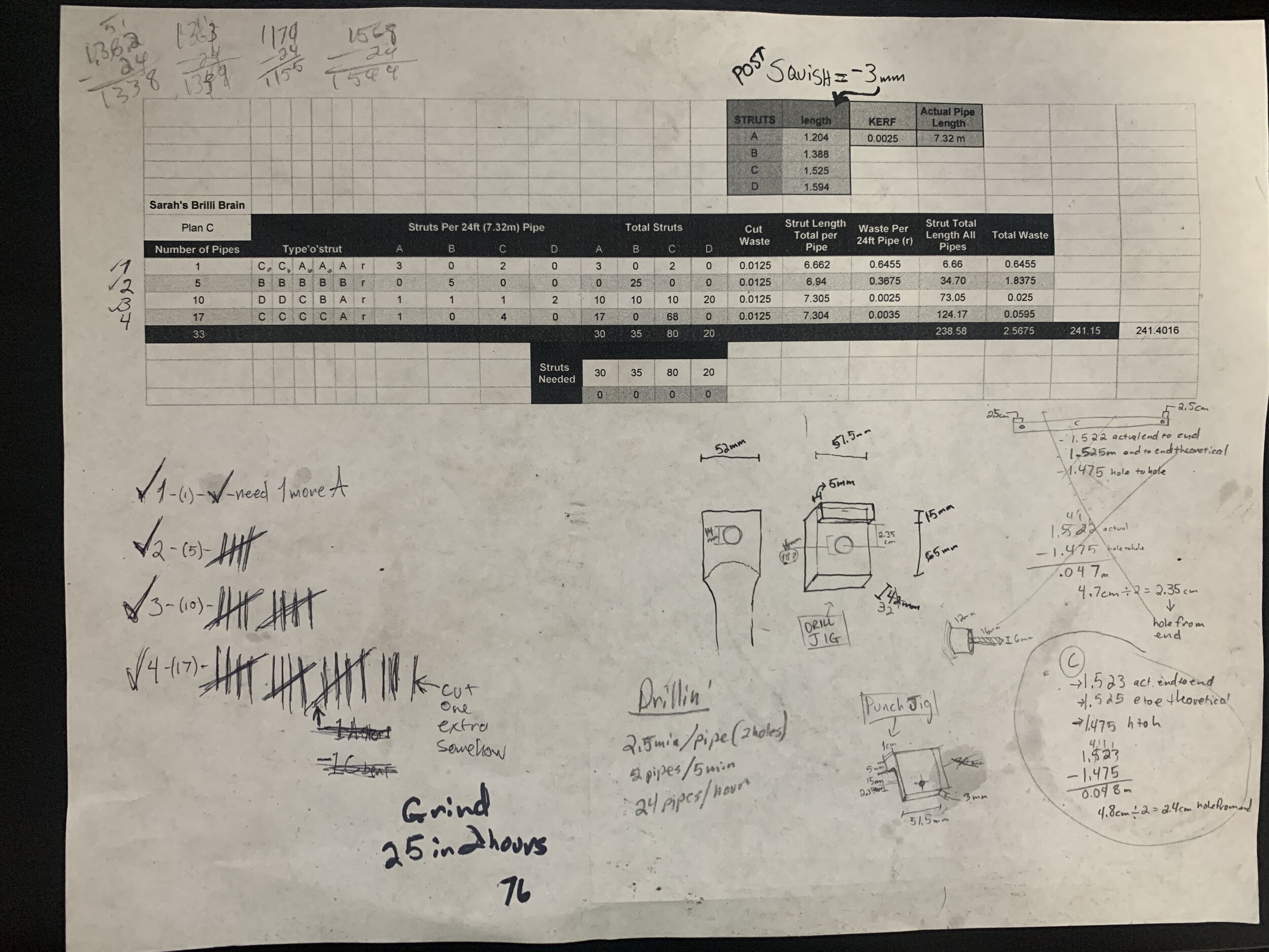
When constructing a dome with bolted joints, you have to remember to add to each strut length given by the calculator to account for the flattened end and the hole you have to drill, because the dome calculator gives you the length of the side from vertex to vertex. As mentioned we used 2.5cm extra on the end of each strut length. Given that, we have to cut 30-A length struts at 1.204m , 35-B at 1.388m, 80-C at 1.525m, and 20-D at 1.594m. Now we needed to know how much pipe to order, which means figuring out how to maximize the number of struts you can get from each pipe with the least amount of waste. Don’t forget to include the cut width, or “kerf”, of the sawblade!
SPREADSHEET TIME! That is the Spreadsheet we both came up with to keep track of everything. Sarah was excited ‘cause turns out she’s a wizard at spreadsheets. I found a bunch of online cut length optimization calculators that are made for contractors (! even paid for one) and went to work on them while Sarah tried to see if she could sort it out on her own. Here is the last version (there were a few iterations) of the spreadsheet she came up with to sort out the optimal way to cut the pipes with her idea next to the website’s. Turns out after hours of checking and rechecking with all of the online calculators we could find, that Sarah came up with a pattern to cut the pipes using 1 less 24’ length than all of the other calculators, and with MUCH less waste, almost 8 meters less, and with fewer cut variations. This was one of the sexiest feats I’d witnessed in a long time. Two of the schemes for the cuts she came up with left as little as 2.5mm of waste. Luckily, the pipes ended up being 7.32m instead of the 7.315m (24’) they are spec’d at. Giving us all of 5mm of slop. That sorted, we ordered 34 (33+1 spare just in case we made mistakes in production) lengths of 24’ pipe and decided to pay the $65 to have it delivered, as cuts were $4 each if you pay them to do it. You can see the costs of everything on this sheet of the spreadsheet.
PRODUCTION
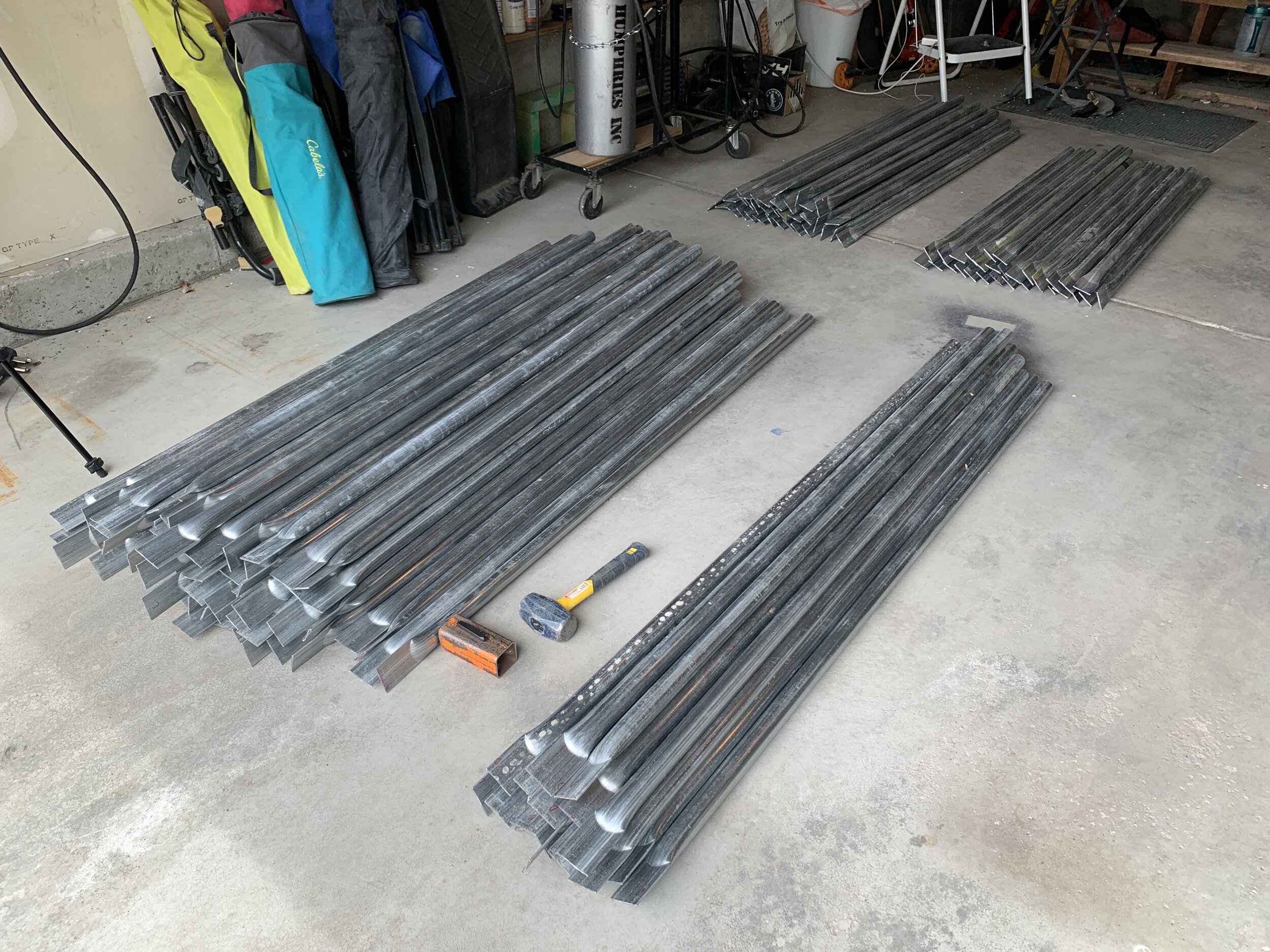
Cutting
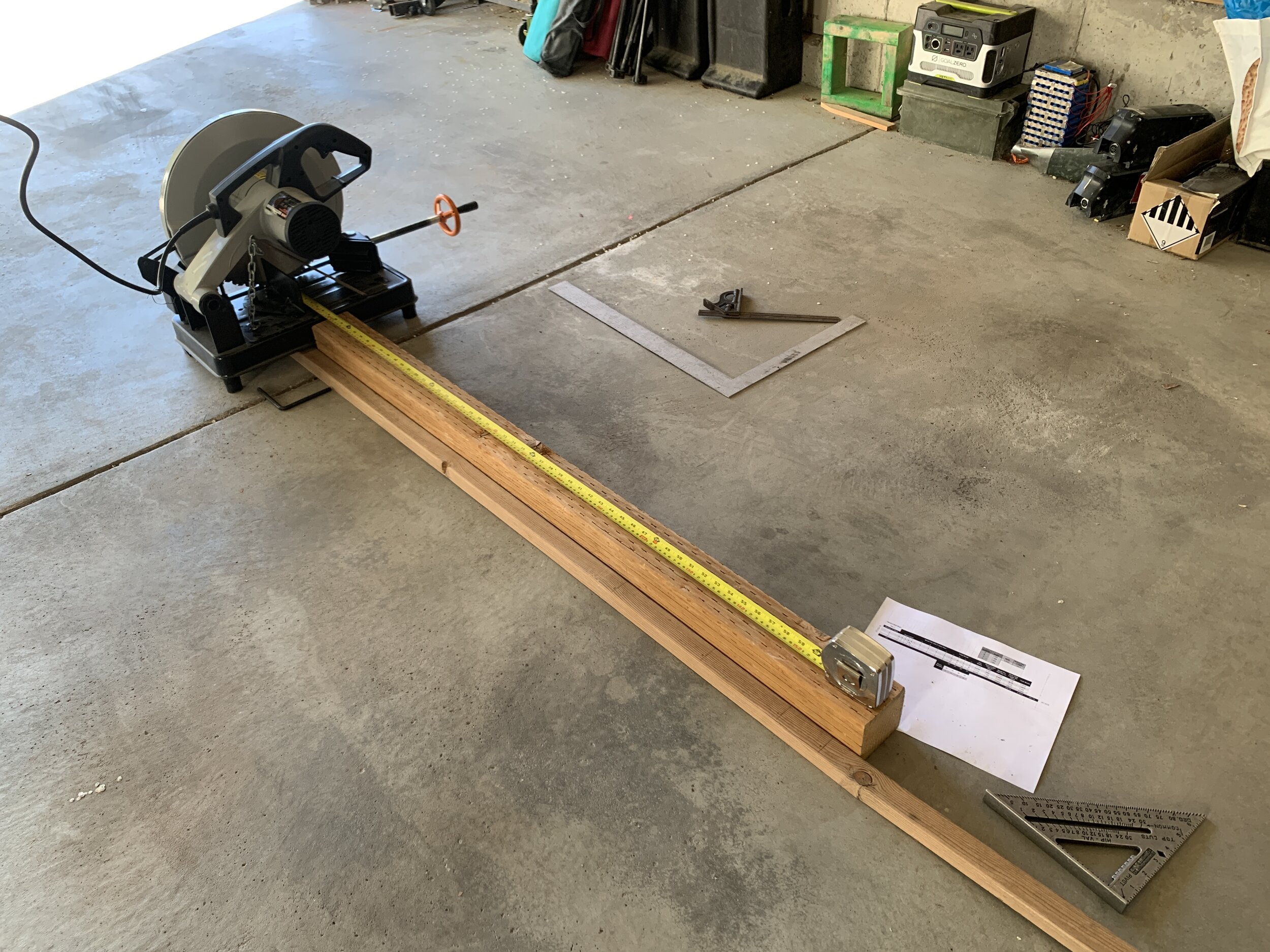
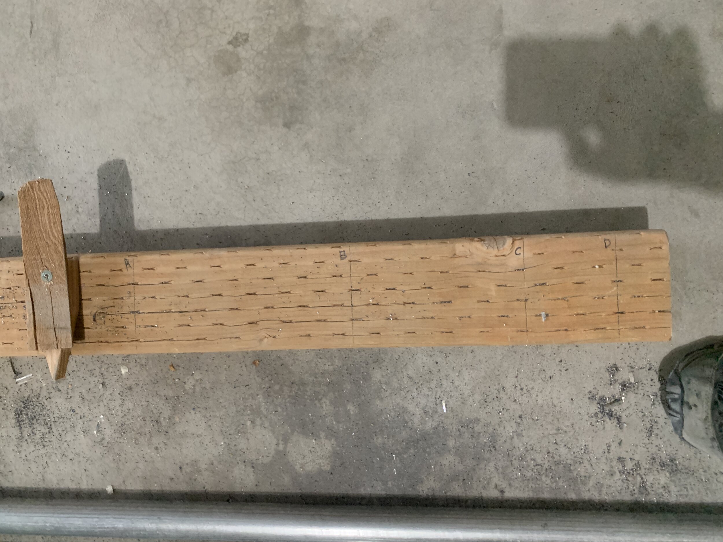
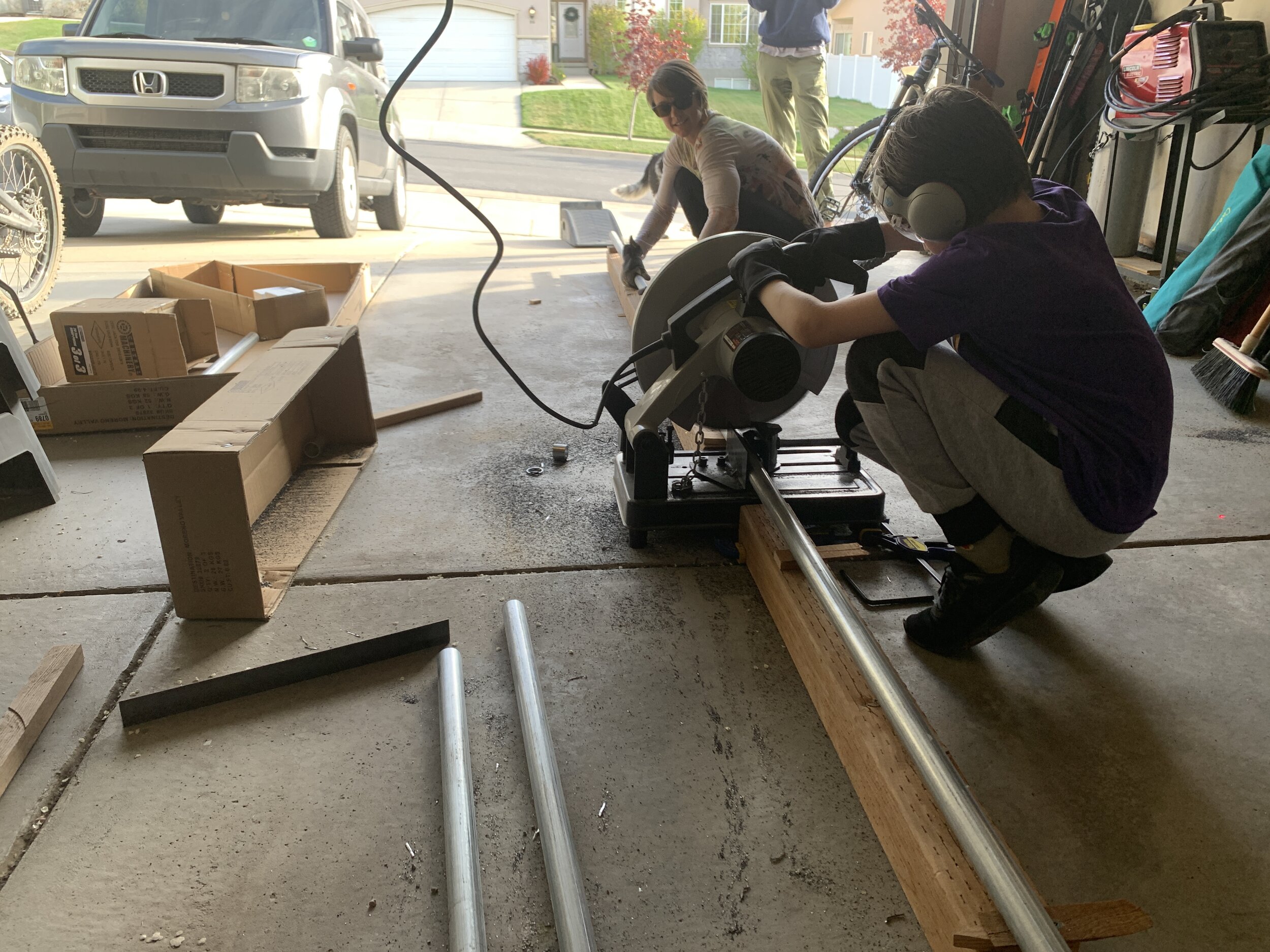
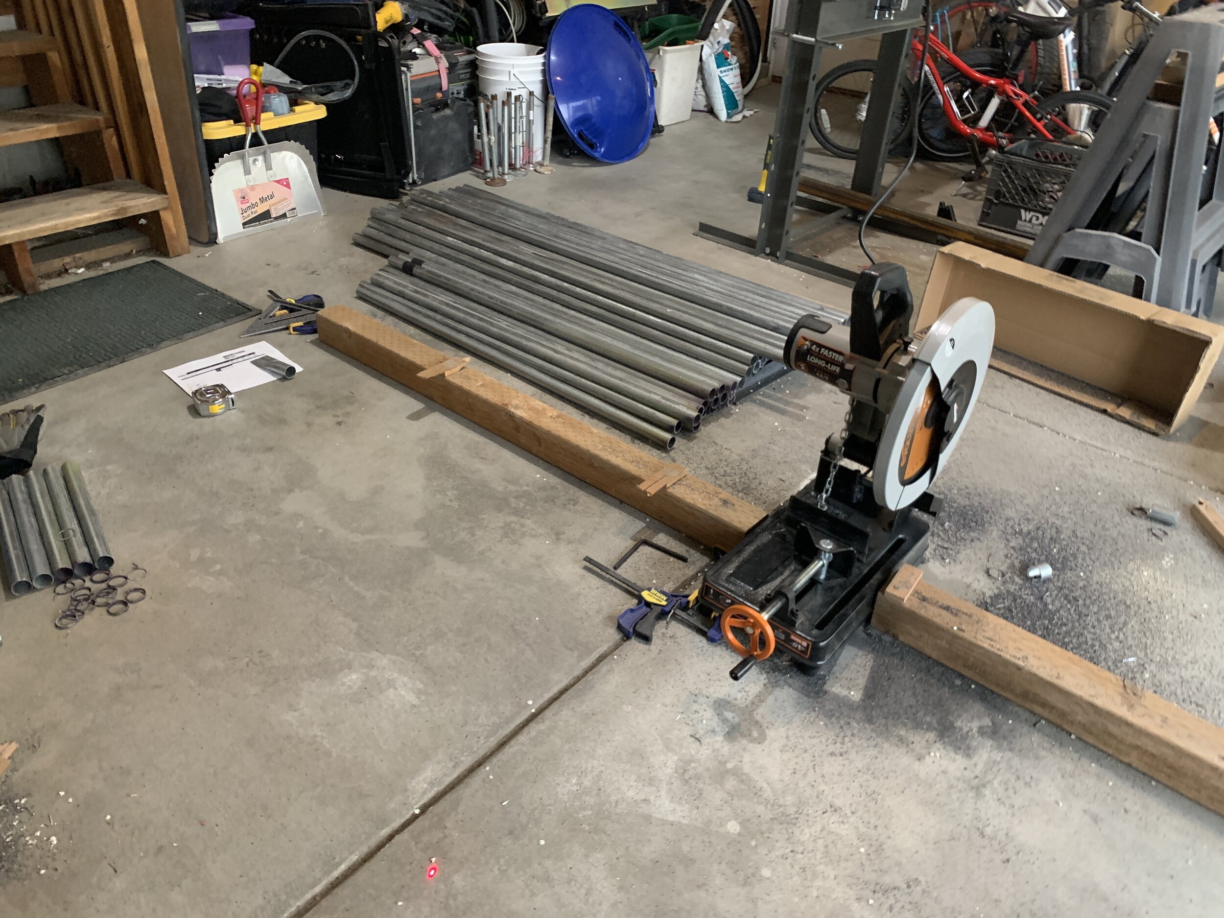
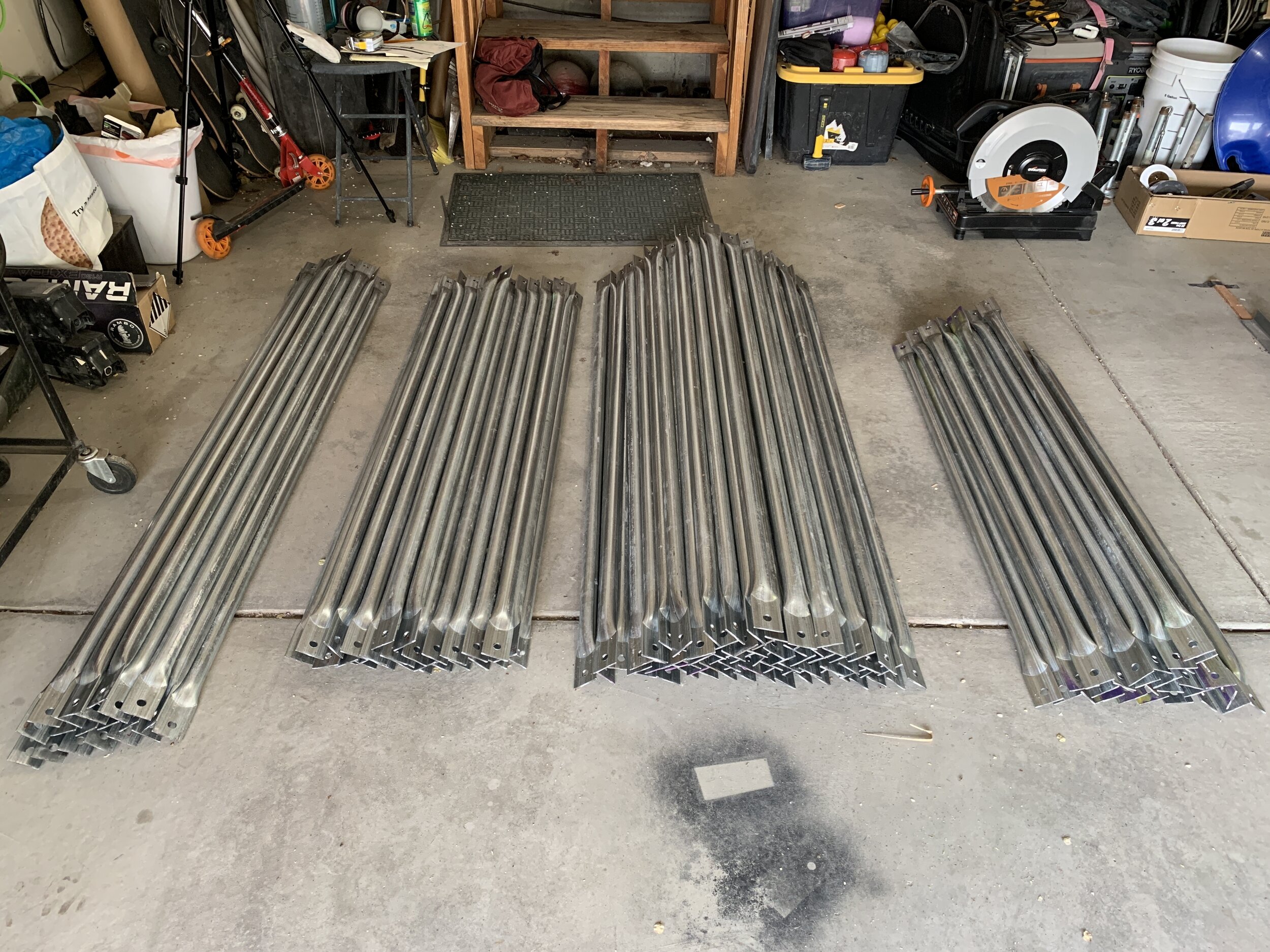
Pipe delivered, time to cut some pipe. How much inches of pipe you want? I already owned an Evolution RAGE2 14-inch Multipurpose Chop Saw, which is an amazing cold cut saw I highly recommend for stuff like this. So I rigged up a jig with a 4x4 I had laying around by slapping it to the side of the saw and measuring from the blade and marking on the wood the lengths of each strut. I tried making a stop various ways but since I would have to move it a number of times for each pipe, I ended up eyeballing the pipe end against the line on the wood which worked perfectly. Ended up with about +/- 1mm of accuracy in the cuts.
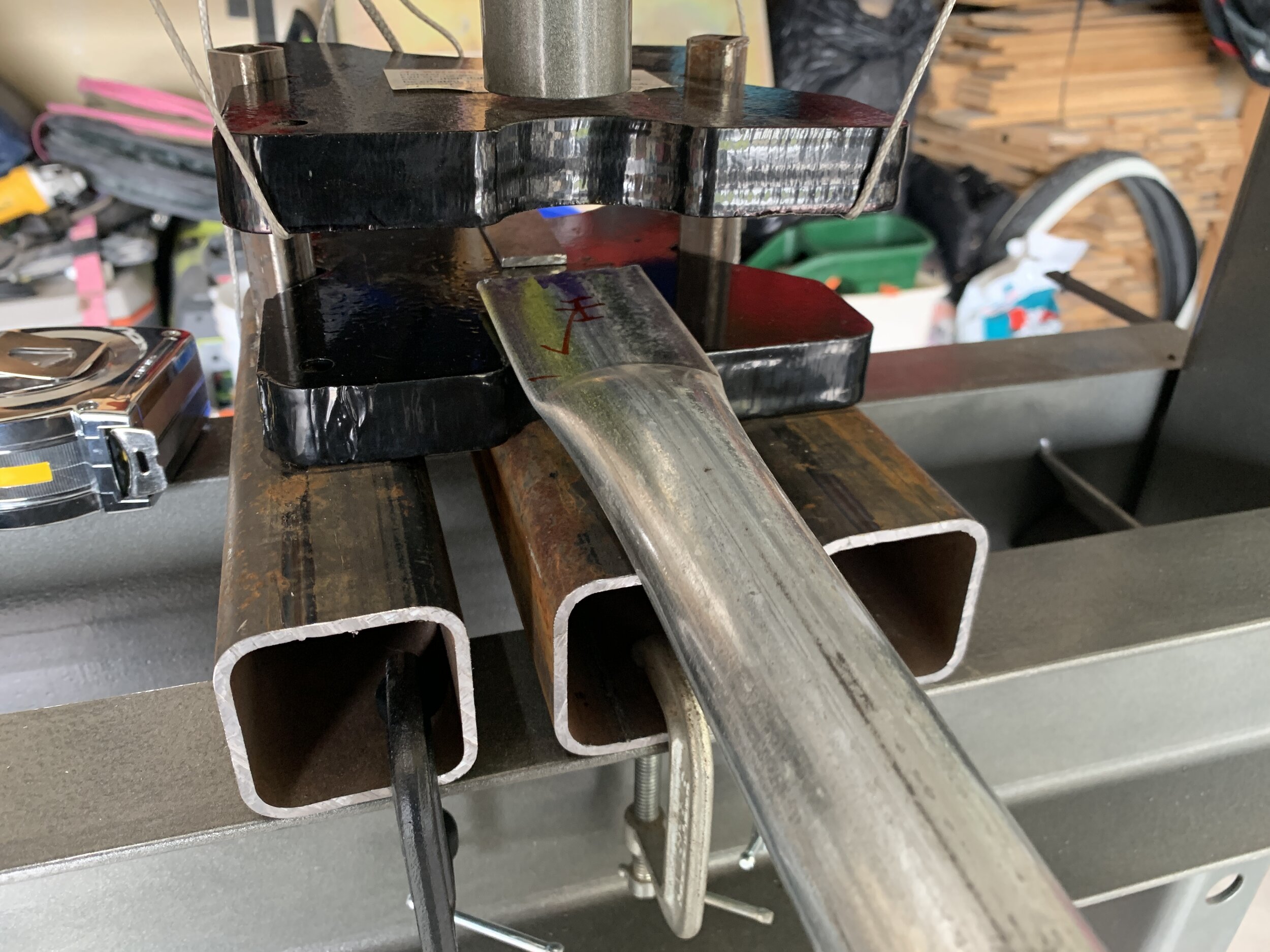
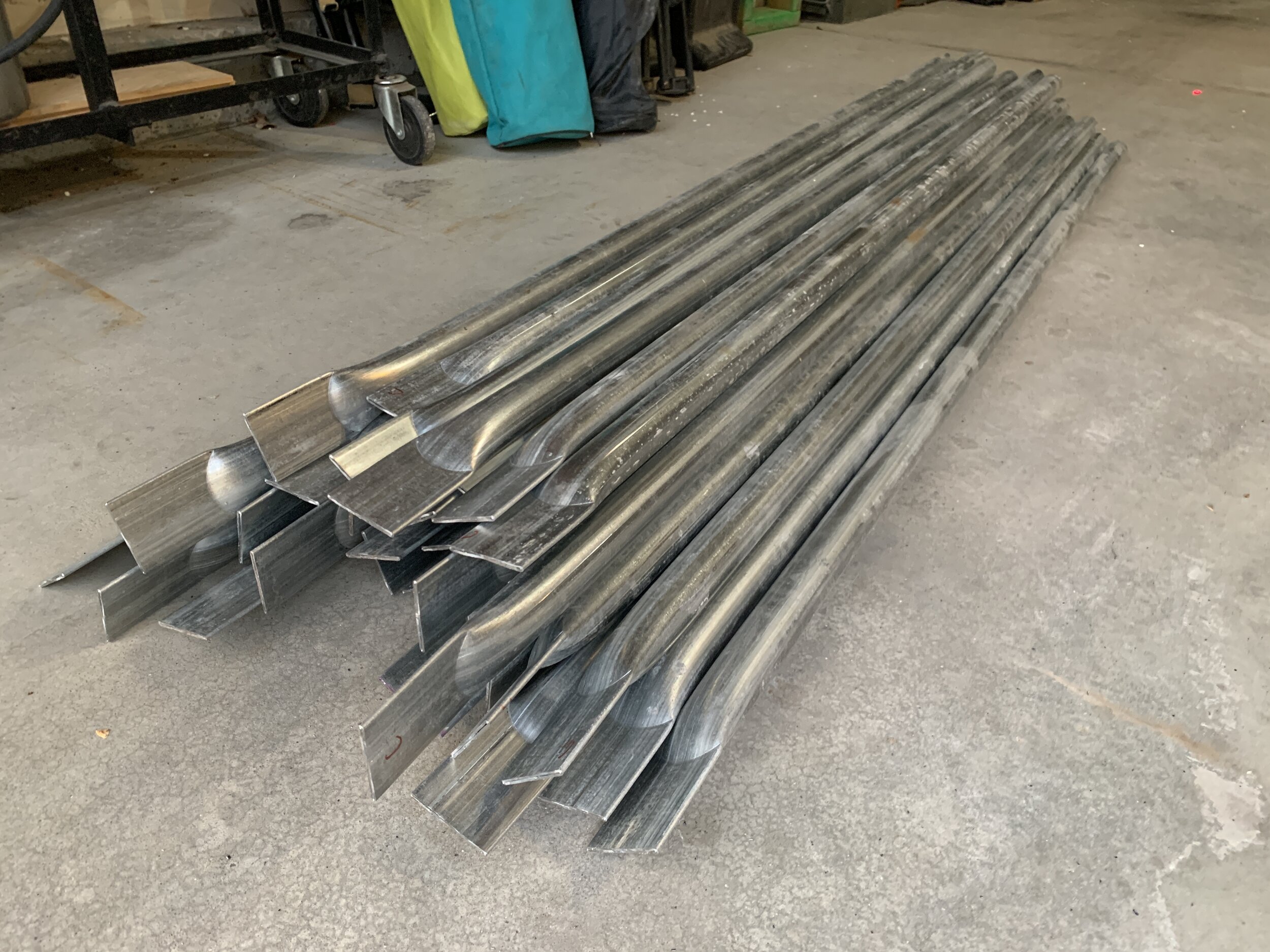
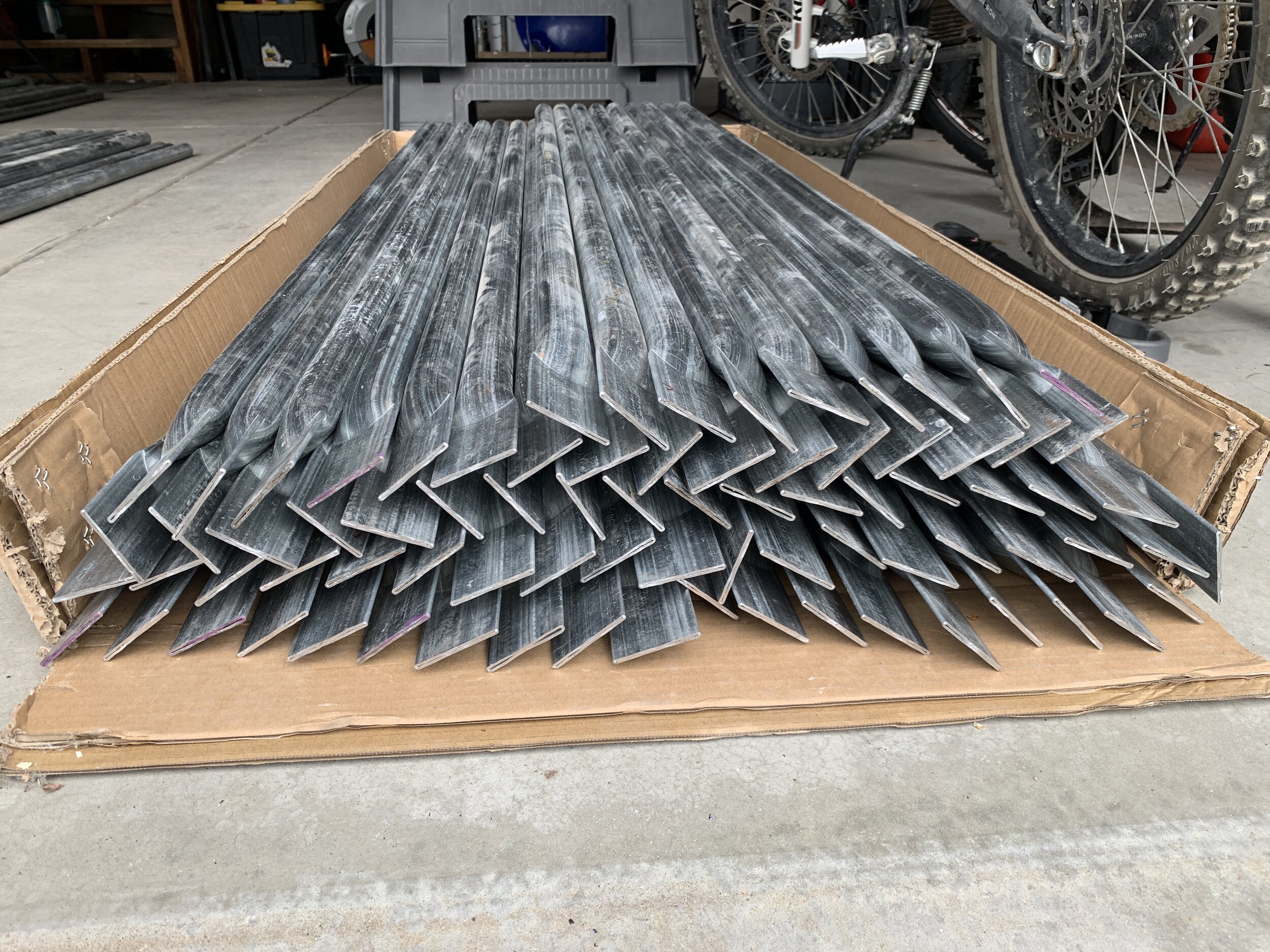
Flattening
Once all the pipes were cut, it was time to use the 20-ton floor press to flatten the ends. We used a couple of saw horses to rest one end of the pipe on and to make sure the flattened ends were on plane with each other when we pressed the other end. Also, make sure the pipe weld seam does NOT get flattened at the 3 or 9 o’clock side of the pipe, this can cause the pipe to split. The jig I built worked really well and other than having to re-weld a couple of the tack points due to bending, it held up. It took about 35 pumps on the bottle jack to squish each end, and there were 330 ends to squish plus tests… so I figure between River, Sarah, Rich and I, we pumped that jack almost 12,000 times. This being Harbor Freight, one of the ends of the cross bolts holding the crank arm together broke out of it’s bracket at some point, so we used a C-clamp to hold it on until we finished. It was also leaking oil by the end, but it held up otherwise.
Marking the different strut lengths so you know what goes where when building or taking apart is a good idea. It’s often suggested to paint the ends a color, but I’ve seen the paint flaking off on playa on some domes done this way, and I wanted a clean lookin’ dome, so I took a queue from the DOTA dome and got metal stamps to mark each end of the struts A, B, C or D, on both sides. Rich and I took turns stamping as we were flattening ends. Glad we did as this was super helpful for checking during assembly.
Drilling
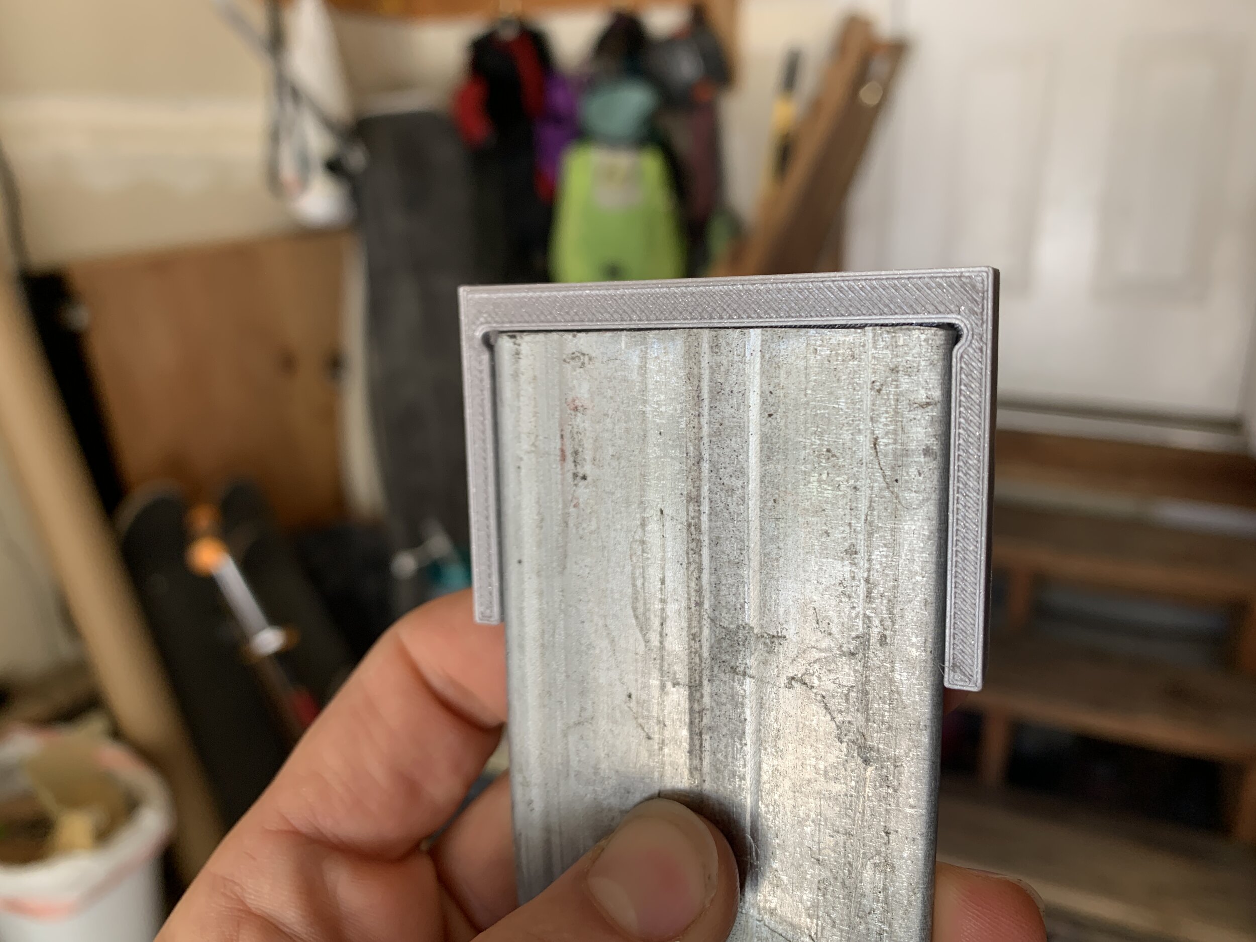
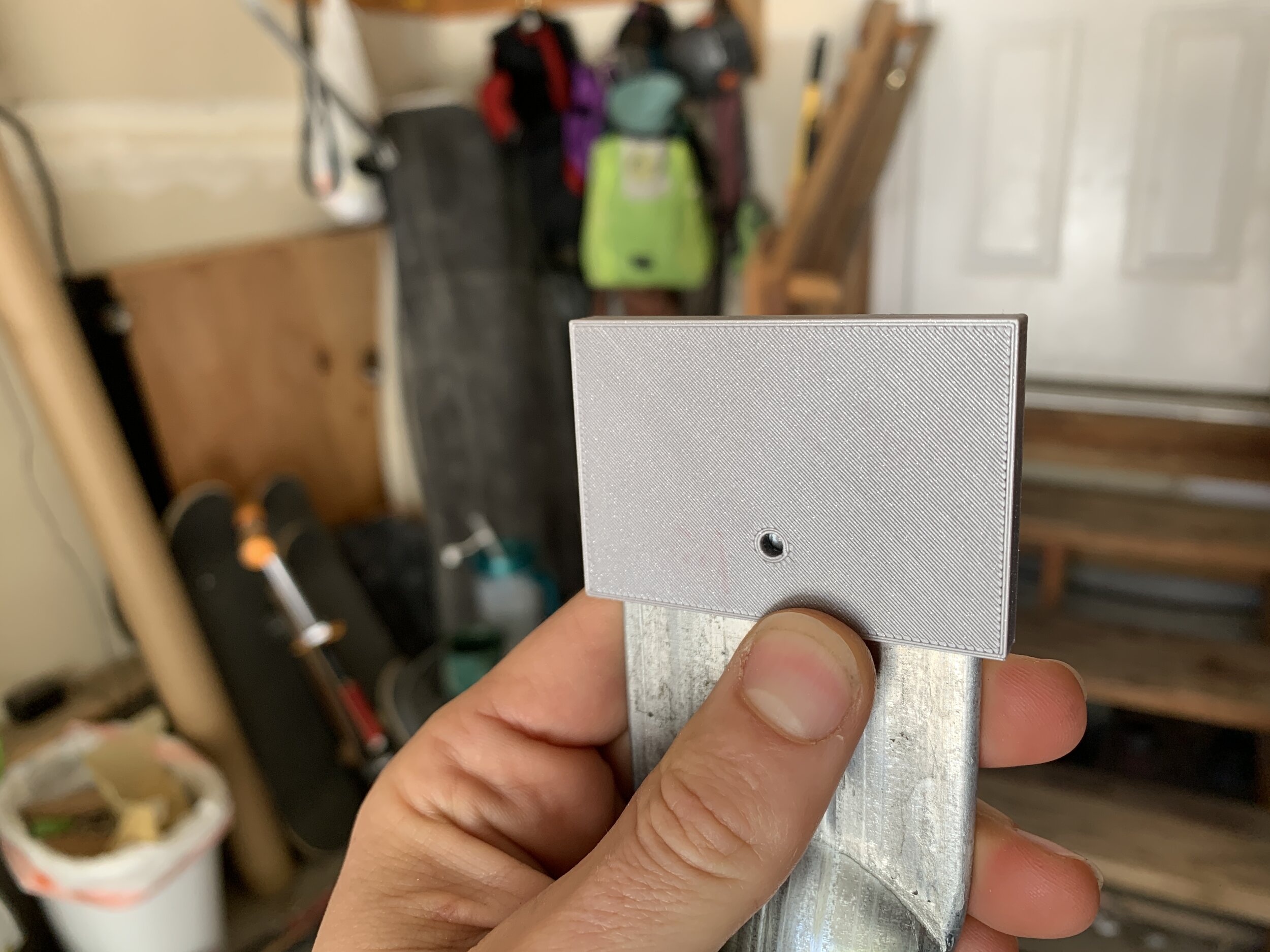
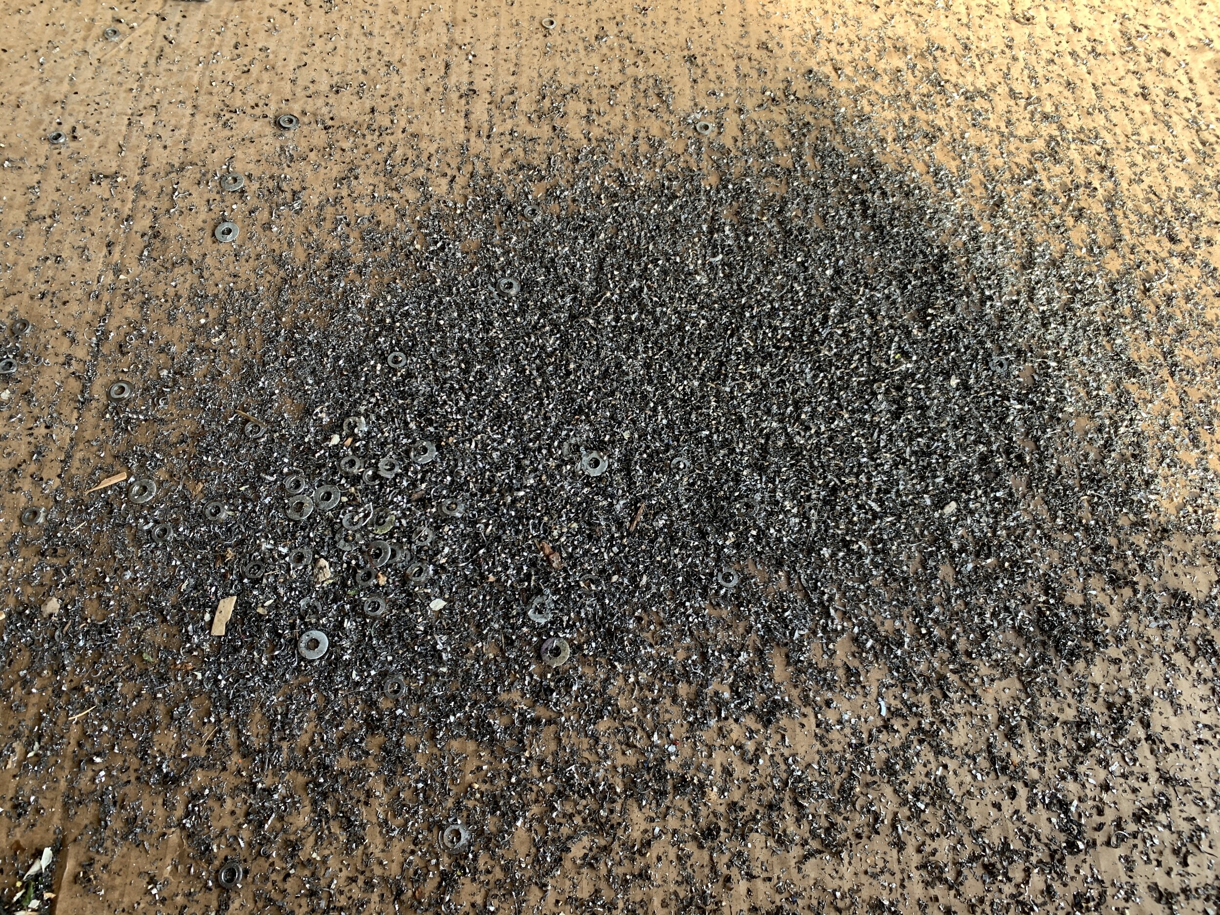
Next I drilled all the ends. 330 holes. Thankfully our friend Melissa’s father let us borrow his beast of a floor stand drill press for a week so we didn’t have to buy one. Again, we planned to drill 14mm (9/16”) holes 2.5cm from the end… turns out the flattening shortened the struts by between 1mm and 1.5mm on each end… so I changed it up to drill the holes 2.4mm from each end. I made a jig in Fusion 360 and 3D printed it to use on the ends with a center hole punch to mark the drill spot. This worked fantastically. I also made a jig to place in the vice… this was a disaster. Turns out metal gets real hot when drilled and PLA plastic melts readily. In retrospect… obviously.
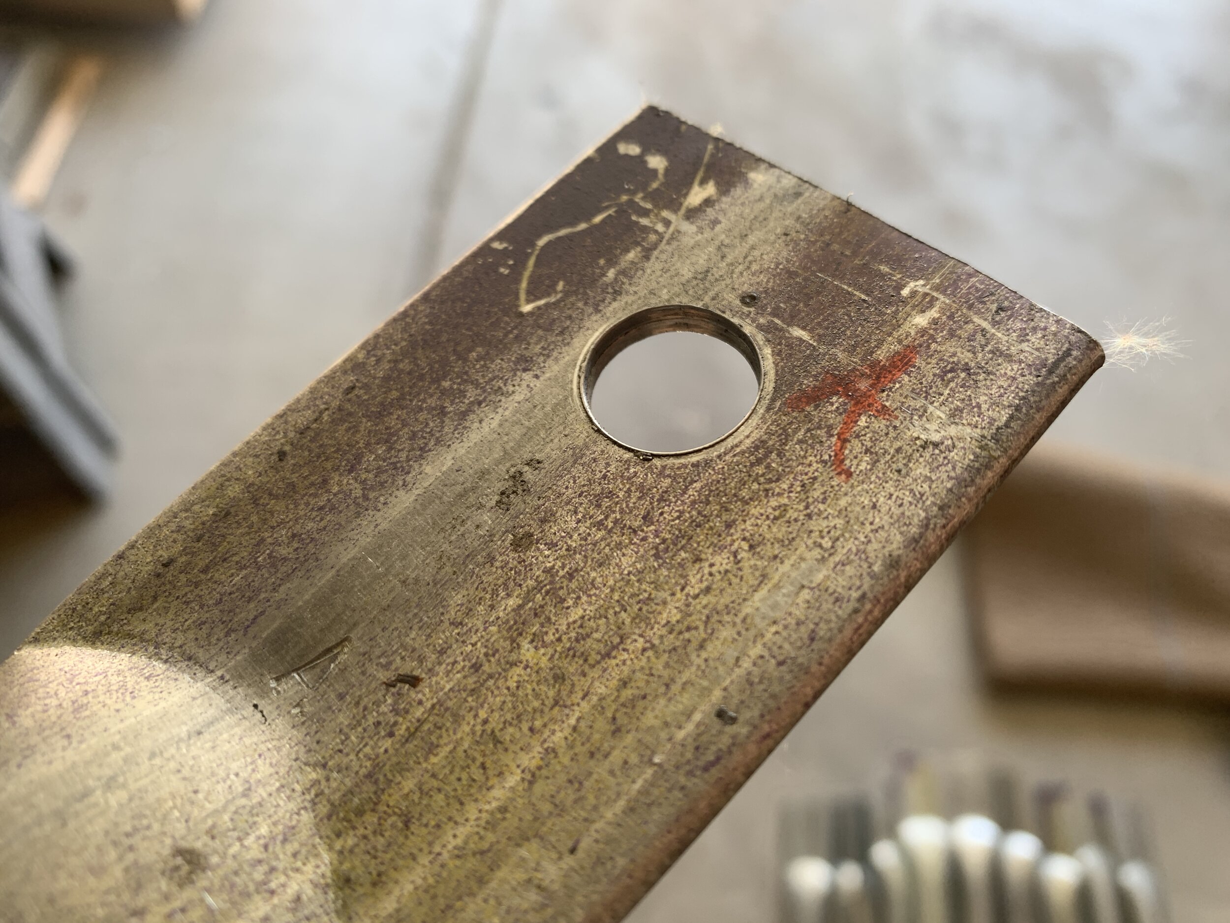
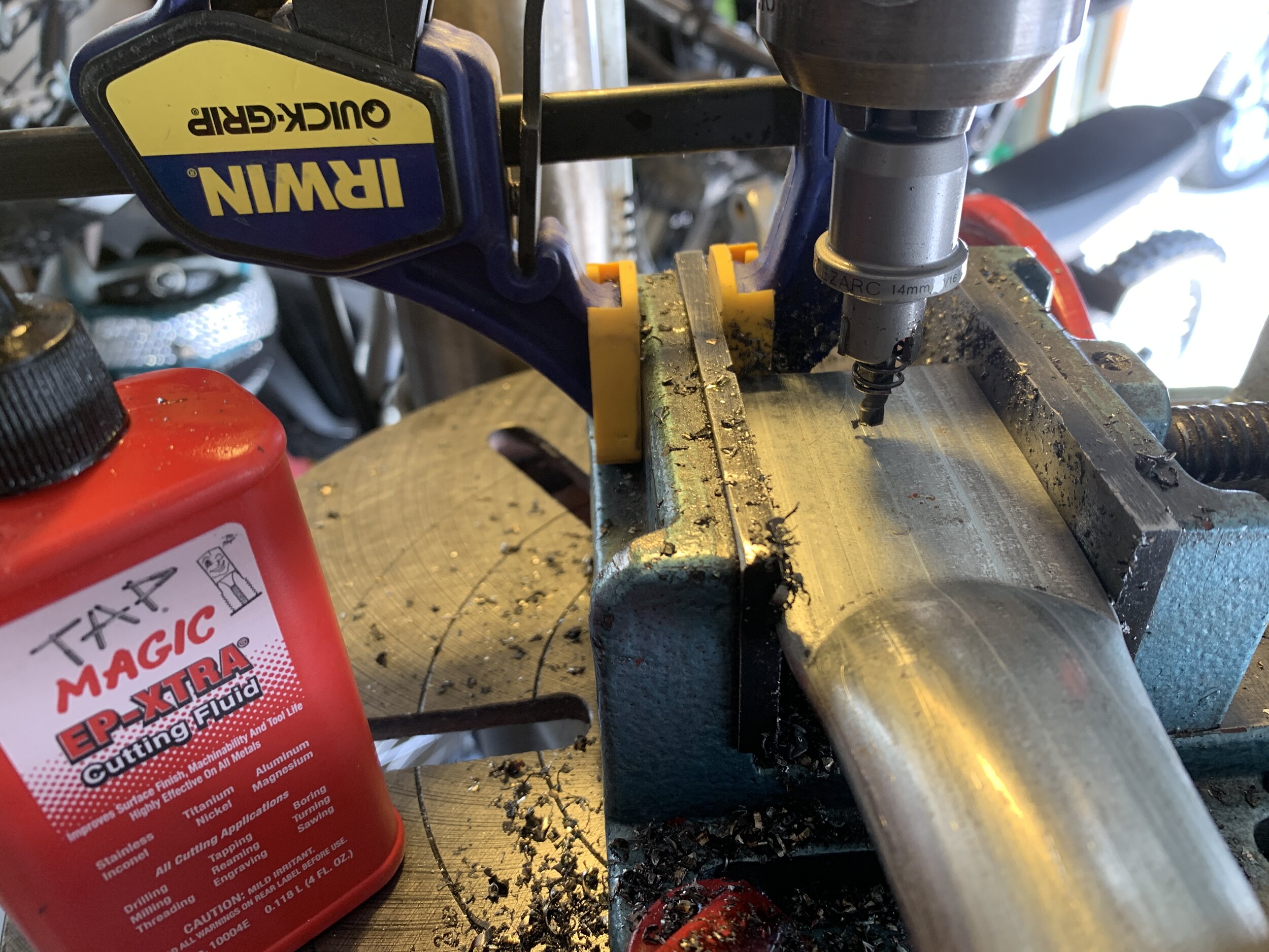
Since the hole I was drilling is so big, it’s a bad idea to go straight with the full size bit. You either need a step bit or to drill a series of larger holes (which would take forever). I stumbled across hole saw style bits at some point and decided to give it a go based on all the good ratings. I was skeptical, but this EZARC Carbide Hole Cutter Heavy Duty for Stainless Steel worked amazingly well along with lots of Tap Magic Cutting Fluid and a needle tip. I had the drilling down to about a 2.5 minutes for each strut, both holes, so about 25 struts per hour.
Grinding
Ridiculous sketchy shop tool setup of the day.
I wanted to round the ends of the struts so you could reasonably safely climb all around the dome without worry of being sliced by razor sharp steel, and to make assembly/disassembly/transport safer. Trying to save cash as always, I rigged up the DeWalt angle grinder I have to the H-frame of the floor press with clamps, threw on a grinding wheel, and went at it. Sketchy DIY shop tools for the win. This was by far the most grueling part of the build. It took about 2:30 to 3 minutes per strut and was exhausting, LOUD work.
With about 20 struts to go, the grinder started to slow down, then let it’s smoke out… see video below. I unplugged it and put it outside waiting for it to catch fire, and it stayed too hot to touch for over 5 hours. I guess they aren’t made to be run for 2-3 hours straight. Luckily our friend Dustin lent us his bench grinder to finish the job. If I had to do this over again I’d either borrow or buy a very large bench grinder with two different grit wheels. It would have likely saved some time and effort… and an angle grinder.
Bending
The flattened ends of the struts all need to be coplanar so a bolt can go through them, which means they all have to be bent because the struts all meet at an angle which differs for every strut. The calculators can tell you the required angle for each size strut. From previously building a dome, I knew there was an amount of flexibility here when constructing the dome and 1 degree won’t make or break the build, so I rounded the required angles so that all A struts (which are the shortest ones that make up the 6 pentagons of the dome) were bent to 10 degrees, and all other struts to 12 degrees.
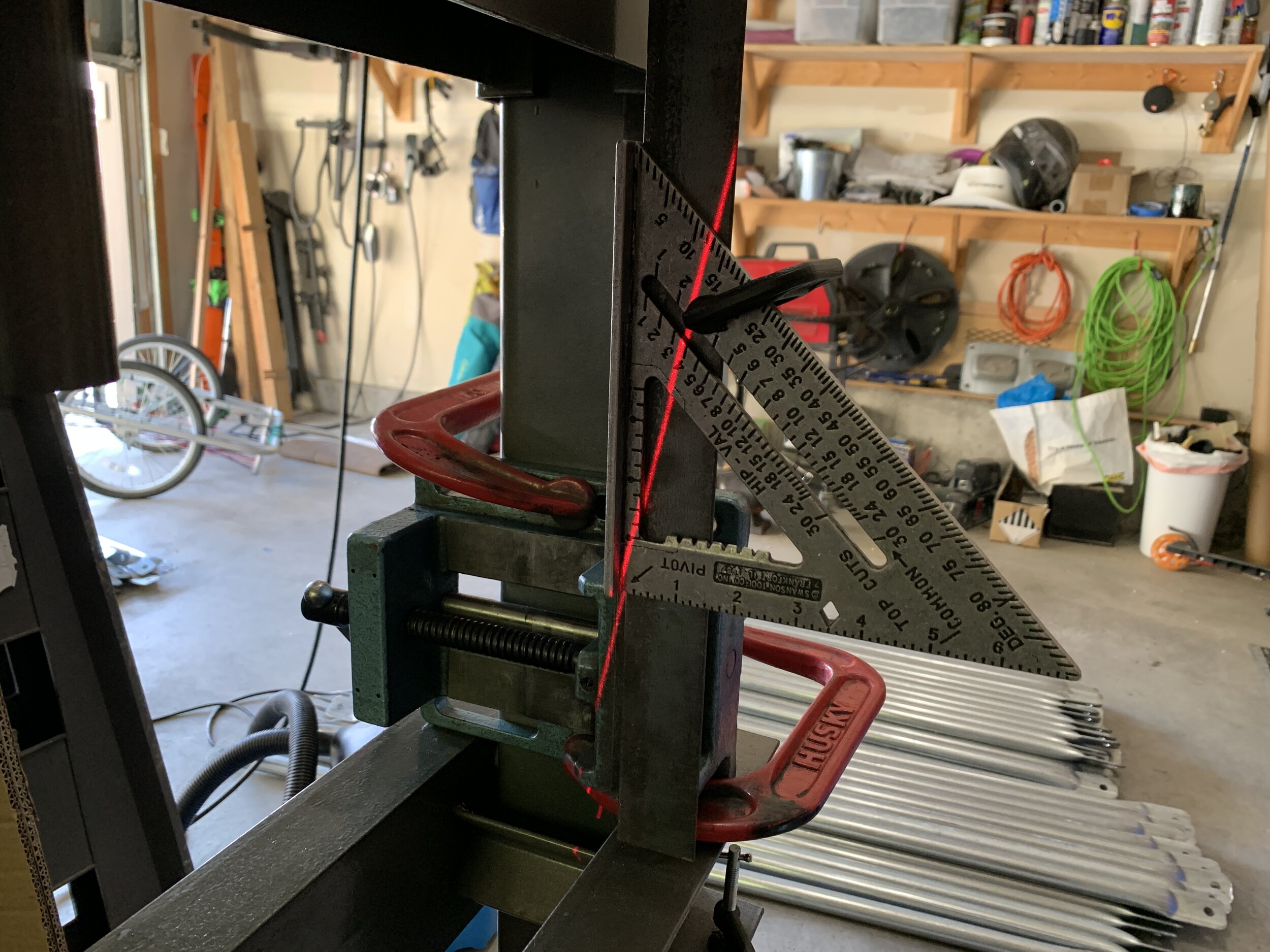
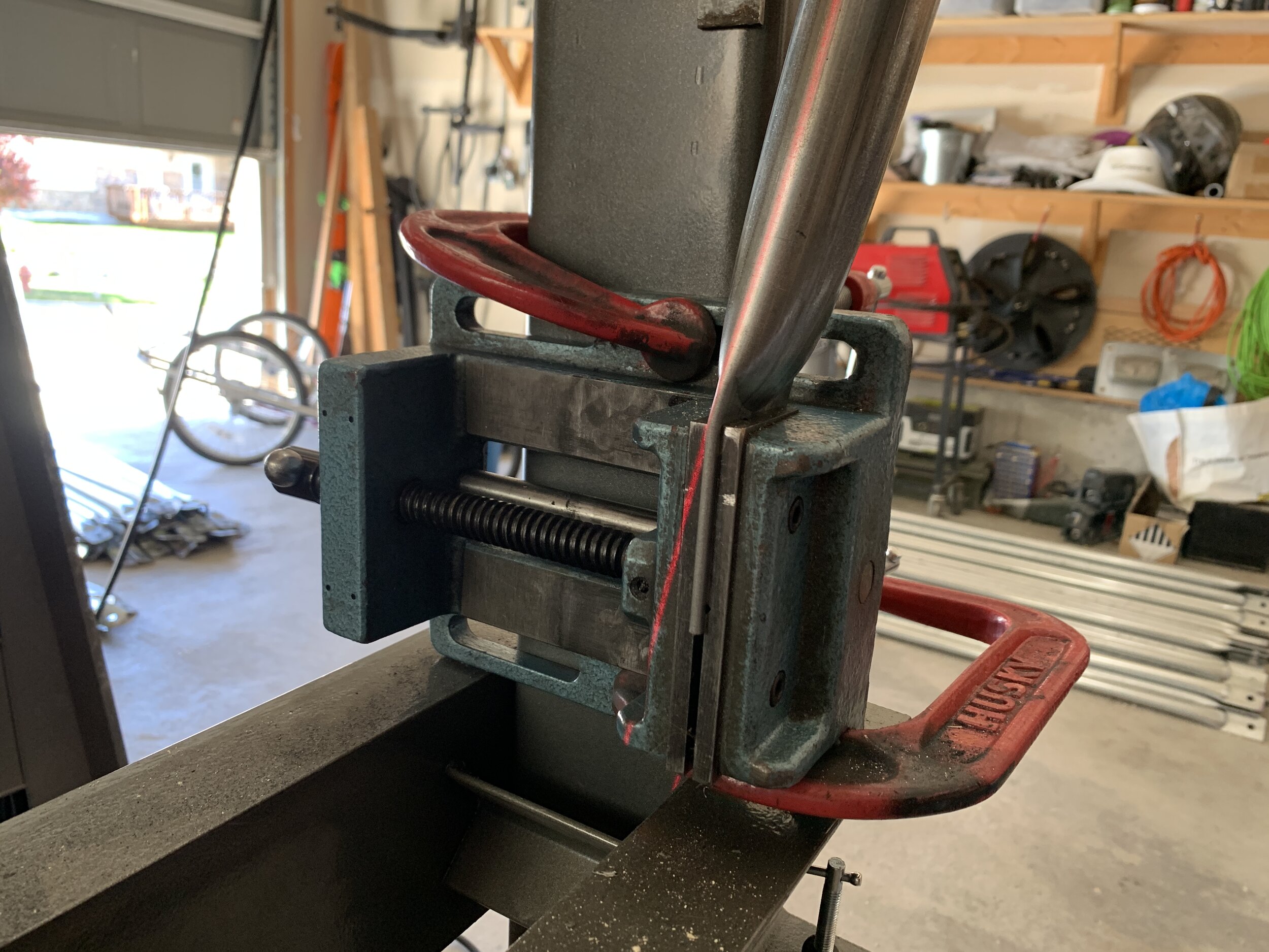
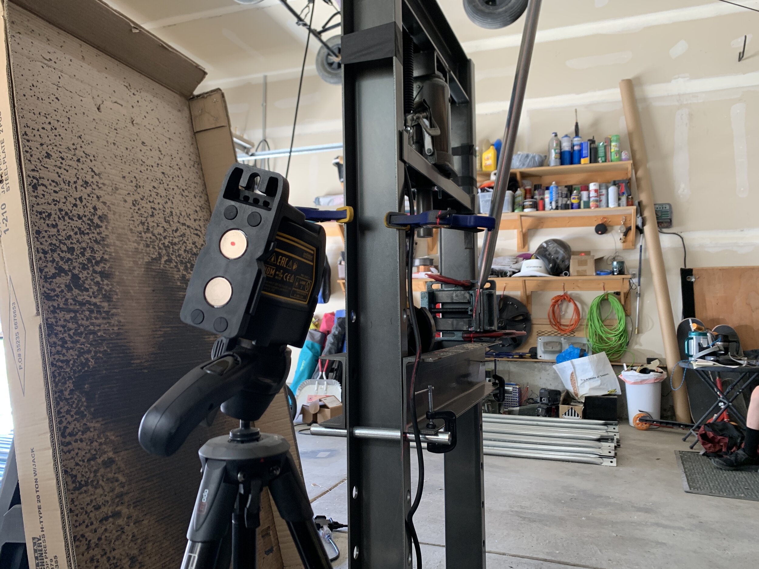
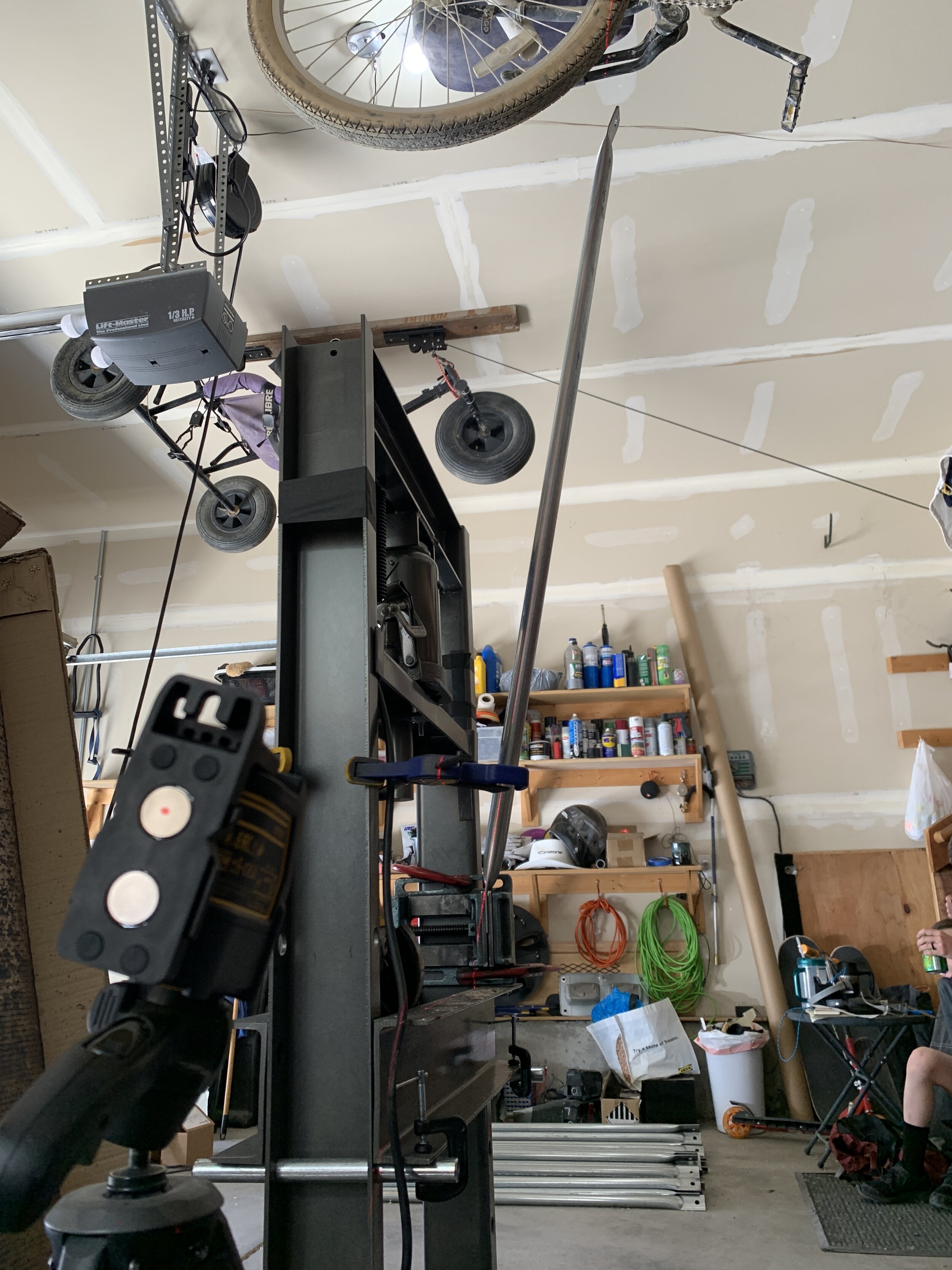
Trying to come up with the fastest way to do the bends, I decided to clamp the drill press vice to the vertical side of the floor press frame so we could drop the poles in quickly, close, bend, rinse repeat. I tried using a stop block as many builders suggest but the results were inconsistent. When you need precision… you need lasers! So put my laser level on a tripod, and used a carpenter square clamped to a piece of angle iron in the vice to align the laser to 10 and 12 degrees. This allowed us to clamp the end in and bend the pipe til the left side of the flattened end lined up with the laser with great accuracy. Sarah and I got into a good rhythm with this process and it went pretty quick. This was the last step before build. We recounted everything, and I made one more strut of each length with the leftover pipe just in case.
BUILD

Sunday, May 10th, 2020 was build day. It took Sarah, River, Matt, Nikkita, Carey, and I about 6 hours of leisurely building to get it done, but it felt way faster. Using the Domerama assembly diagram, we used two ladders to alternate holding and bolting as we went around, building from the base up.
We laid out each “layer” or “row”, double checked the lettering pattern, then bolted each joint together without tightening the nut. We made sure to keep the pattern for each joint of lowest strut layer on the inside. If the struts were on the same layer, the rightmost strut was on the outside. Once the layer above it was build, I’d go around and tighten the lower layer with the impact driver.
I got this method from the Pacific Domes build video I’d watched a bunch, and it seemed like a good idea so that all of the forces from the upper layers are pushing down “on top” of the layer beneath, but in reality I have no proof this makes for a stronger dome and don’t think it even makes sense. What it does do is make the build much more difficult because for every layer you build, you have to remove the bolt to add the next later to the top of the others, closest to the bolt head, which is a pain in the ass. If you do it the other way, you can just remove the nut and add the next layer. If I was to do it over again, I’d do it this way, adding each layer to the bottom of the stack. It would have saved us a significant amount of time on the build without a doubt and I don’t think it would have any effect on structural integrity, but I’m not an engineer so what do I know.
We also didn’t prebolt struts above the layer we were working on as they do in the video, as our pipes were thicker and much heavier than what they were using, and we were using much shorter bolts which didn’t allow for room to rotate the struts around once they were bolted like Pacific Domes does. We did, however, pre-build some of the joints for the topmost layers. The final top pentagram was by far the hardest to manage and took us a bit, but that was mostly because we were standing top toe on top of ladders, OSHA approved!, instead of using scaffolding where it would have been easier to get to the top of the joint. Regardless, it was very smooth to put together and we didn’t have to fight the alignment of the joints nearly as much as I’d expected. Simply pulling out the bottom ring a few inches below the problem side of the joint fixed it every time. The only required tools were an impact driver with a 3/4” socket and a 3/4” open ended wrench. The topmost joint used a forged eye nut with a Nord-Lock washer so that Sarah can hang aerial equipment from the apex. Here’s a timelapse of the build:
FUTURE
We are currently planning to bury a trampoline beneath the dome to add to the bone breaking potential. We have no plans to cover it though we might add shade panels in some of the triangles if it seems needed. As mentioned, I am also planning to add a deck to the top so we can sit and see the Salt Lake Valley over our neighbors houses, but that’s for a future post. Will it go to the next burn? Maybe.
Duct tape for picking
If you have to remove a lot of adhesive backing paper from acrylic, use duct tape. I just figured this out and it is going to save me many hours of picking with an exacto knife!

Walnut Audi badge for Pro Clip iPhone mount
I couldn't stand looking at the "ProClipUSA.com" bubble sticker on my new iPhone mount so I quickly made this badge to match up with the walnut interior trim. Should I make more?


How to measure line length in Adobe Illustrator
While trying to figure out how long some lines would have to be for my paraglider project, I realized there's no obvious easy way to measure line length, or multiple line lengths, in Adobe Illustrator... until I figured this out.

Select in the menu Window -> Document Info. In the floating window that pops up click the options menu pull-down in the upper right and select Objects. POW... there ya go. Measurements are shown for the total length of whatever lines you have selected. The units are changable in the Units panel of the main preferences. Awesome.
A little paragliding nerd time
I've decided to finally finish a "salable" design for my laser cut paraglider. I'm working on the final cut files now and finishing up the little design details. Here's part of it... a pilot! This is version 3, Getting the balance correct through trial and error.

balance
I want them to have actual paragliding line and luckily I have a ton of that. Making line rigs and tying hundreds of knots should be fun!
Walnut veneer for iPhone backs
I decided to do some walnut iPhone backs for friends after my successful etching of my own etimoe iPhone back from Monolith.
I ordered some .03" walnut veneer with sticky back from Inventables. I'm sure not the cheapest but they are fast and reliable quality wise so just for a couple of test sheets... they'll do.
After a few test cuts and engraving it's looking like it cuts nicely at Speed 90 Power 60 and engraves well at 1000 DPI at Speed 100 Power 30.

It looks nice with just some mineral oil/beeswax finish but I've also ordered some OSMO Polyx Hard Wax Oil, which is ridiculously expensive but I've been told is worth it by Monolith.
I'd love to hear if anyone has other sources for veneer with adhesive back!
The dimensions for all Apple mobile products are available on their developer page btw.
iPhone wood back etching - Dusting off the cobwebs
I've had a Monolith wood back on my iPhones for years. I love the feel of the wood instead of the glass/metal backs. Having not done any laser work lately due to other work obligations, I decided to do a quick etching on my phone back. Here's the results.
If anyone is interested I'd love to make more. Let me know ;-)
